Eureka AIR delivers breakthrough ideas for toughest innovation challenges, trusted by R&D personnel around the world.

Aircraft structural strength test loading level

A strength test and aircraft structure technology, applied in the direction of strength characteristics, measuring devices, instruments, etc., can solve problems such as torsional instability, uneven force on connecting cables, and reduced bearing capacity, so as to increase the turning radius and practicability Strong, avoid bending effect

Active Publication Date: 2014-03-12
CHINA AIRPLANT STRENGTH RES INST
View PDF3 Cites 11 Cited by
  • Summary
  • Abstract
  • Description
  • Claims
  • Application Information

AI Technical Summary

Problems solved by technology

[0005] b) If the gap between the channel steels is too small, the connecting cables will be squeezed, resulting in uneven stress on the connecting cables, and there is a risk of premature failure of the connecting cables when the lever bears a high load;
[0006] c) When the gap between the channel steel is too large, the force of the connecting steel cables at both ends of the lever will not be in the same plane, so that the lever is subjected to torque, and the torsional instability is prone to occur when the lever bears high load;
[0007] d) When the distance between the channel steels is too large, the connecting steel cables cannot be restrained, and the steel cables are easy to break away from the channel steel gap, and hang on the outer edge of the lever. During the test, the lever loading is inaccurate, and there will be failures due to the sliding of the steel cables. The abnormal noise caused needs to be carried out at a high place for troubleshooting;
[0008] e) The diameter of the connecting bolt is too small, the turning radius of the connecting cable cannot meet the requirements of use, the cable is subjected to bending and shear loads, the bearing capacity is reduced, and there is a risk of early failure
[0009] These conditions will interfere with the test process, cause test loading risks, increase the maintenance workload of the test process and the danger of working at heights, and will also lead to inaccurate load application, affect the test loading accuracy, and then affect the test results

Method used


Image

  • Aircraft structural strength test loading level
  • Aircraft structural strength test loading level
  • Aircraft structural strength test loading level

Examples


Embodiment Construction

[0019] Below in conjunction with accompanying drawing and embodiment carry out further description:

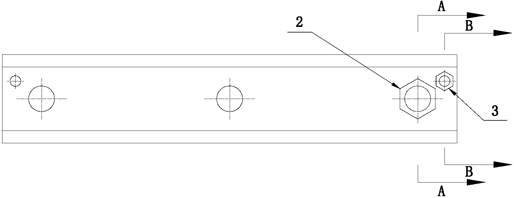
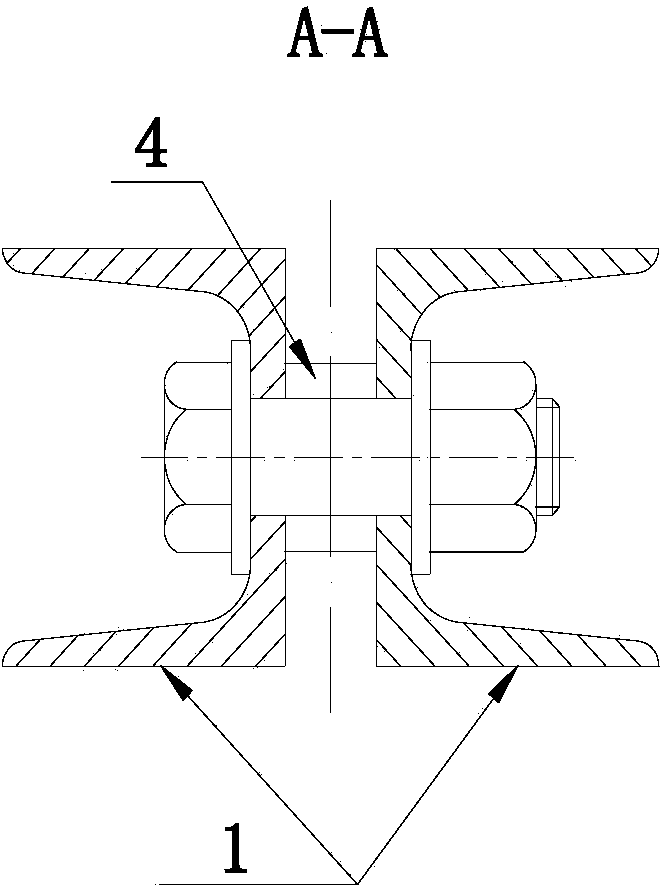
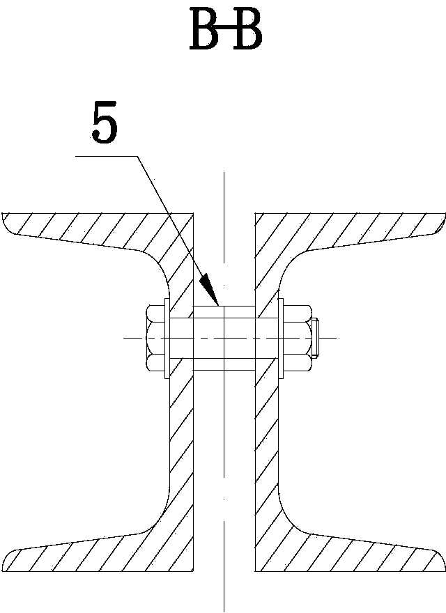
[0020] Please also see figure 1 , figure 2 , image 3 ,in, figure 1 It is a structural schematic diagram of the loading lever of the aircraft structure strength test of the present invention, figure 2 yes figure 1 The A-A cutaway diagram, image 3 yes figure 1 The B-B cutaway diagram. The loading lever of the present invention is composed of 2 pieces of channel steel, 3 connecting bolts (including gaskets and nuts), 3 connecting bolt bushings, 2 positioning bolts (including nuts) and 2 positioning bolt bushings. Among them, the channel steel bears the bending load. Three connecting bolts are arranged on the center line of the bottom of the two pieces of channel steel, which are used to connect the channel steel and the connection between the loading lever and other loading levers, and carry the load transferred by the cable connection. The connecting bolt bushing is...


PUM


Abstract

The invention belongs to an aircraft structural strength test loading technique, in particular relates to a loading level used for fixing an aircraft structural strength test clearance. The aircraft structural strength test loading level comprises two strips of channel steel which are oppositely arranged; a plurality of connecting bolts are arranged on the central lines at the bottoms of the two strips of channel steel; positioning bolts are respectively arranged in positions at the two ends of the channel steel, diverging the central lines, so that the clearance between the two strips of channel steel is fixed. According to the aircraft structure strength test loading level, the clearance between the two strips of channel steel is fixed, and the situation that a connecting steel cord is compressed by the inner sides of the channel steel so as not to uniformly bear force is avoided; the position of the steel cord is limited by the positioning bolts, the steel cord is surely fixed to the connecting bolts; the connecting steel cord is prevented from being separated from the connecting bolt and hung on the channel steel, the force borne by the level can be accurately transmitted to the connecting bolt; in addition, the turn radius of the connecting steel cord is increased by adding a lining on the connecting bolt, and bending and shearing load to the steel cord are avoided. Therefore, the aircraft structure strength test loading level has the advantages of quick machining, simple and convenient use, high practicability and low cost.

Description

technical field [0001] The invention belongs to the loading technology of the aircraft structure strength test, in particular to a loading lever used for fixing gaps in the aircraft structure strength test. Background technique [0002] In the current static / fatigue strength tests of full-scale aircraft structures, the adhesive tape-loading lever system is the main loading form. Between the loading lever and the loading lever, between the loading lever and the adhesive tape, a connecting piece or a connecting cable is usually used to connect. [0003] The loading lever is usually a combination of two pieces of channel steel and three connecting bolts. When using connecting steel cables to connect with other levers and tapes, the following situations will occur during the test loading process: [0004] a) The channel steel gap is uncertain and changes with the force of the lever; [0005] b) If the gap between the channel steels is too small, the connecting cables will be s...

Claims


Application Information

Patent Timeline
IPC IPC(8): G01N3/02
Inventor 夏峰任红云王刚朱亚辉李晓冬付志鹏
Owner CHINA AIRPLANT STRENGTH RES INST
Why Eureka
Eureka Blog
Learn More