Single-phase transverse flux full-control switched reluctance motor
A switched reluctance motor, transverse magnetic flux technology, applied in electrical components, electromechanical devices, etc., can solve the problems of low output torque density, large output torque fluctuation, unable to output continuous torque, etc., to reduce the manufacturing process and cost effect
- Summary
- Abstract
- Description
- Claims
- Application Information
AI Technical Summary
Problems solved by technology
Method used
Image
Examples
specific Embodiment approach 1
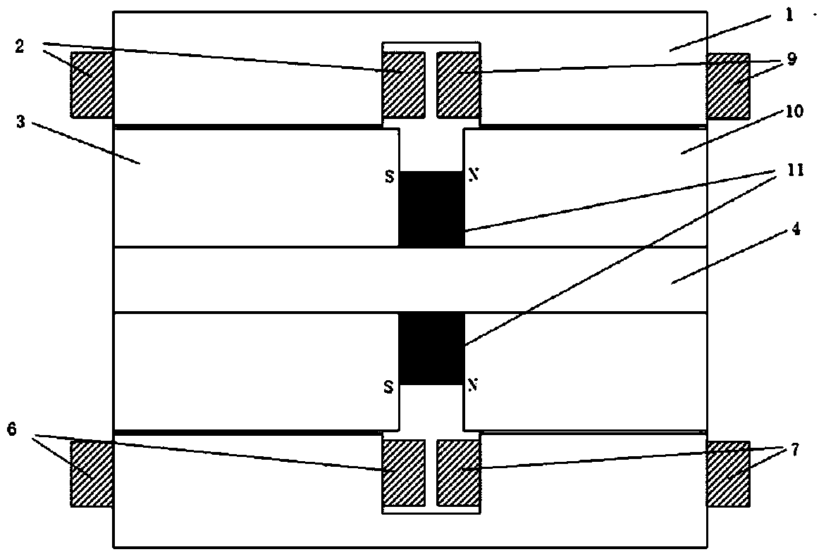
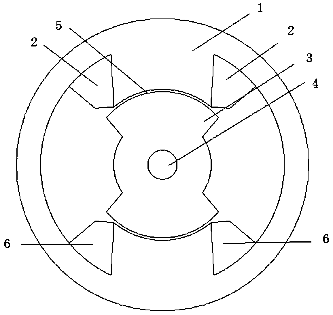
[0020] Specific implementation mode one: the following combination figure 1 and figure 2 Describe this embodiment, the single-phase transverse flux fully controlled switched reluctance motor described in this embodiment has a cylindrical structure, and the switched reluctance motor includes a stator, a rotor, and a motor output shaft 4, and the stator and There is an air gap 5 between the rotors; the rotor is fixed on the outside of the output shaft 4 of the motor;
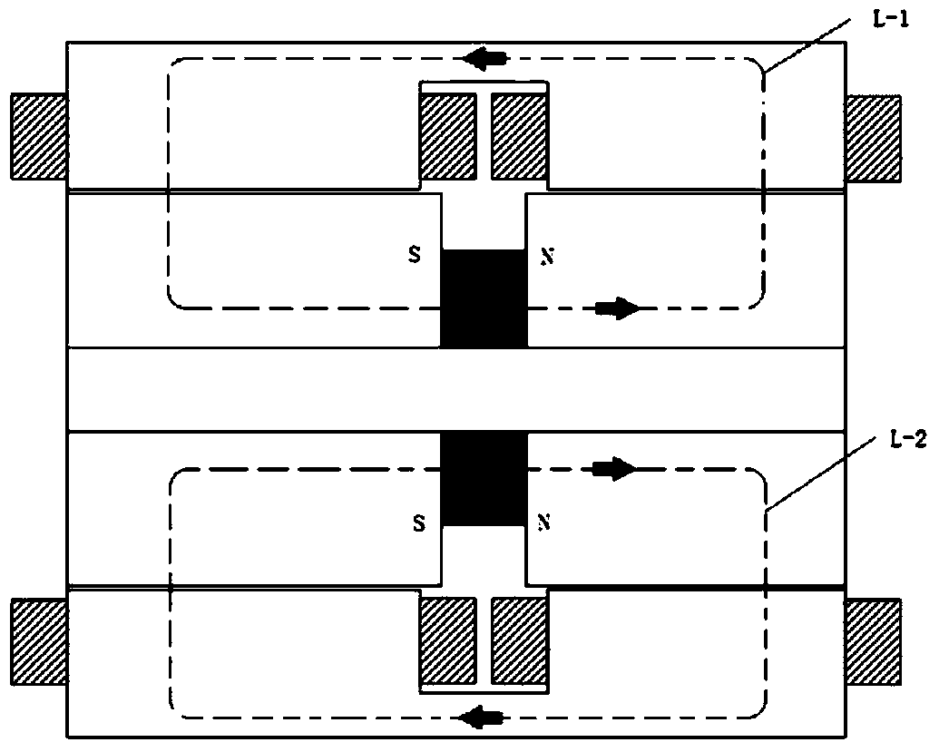
[0021] The stator includes a stator core 1, a front ascending stator winding 2, a front descending stator winding 6, a rear descending stator winding 7, and a rear ascending stator winding 9; the stator core 1 is divided into two sections along the axial direction, namely the front and the rear section, the two-section structure is a mirror-image symmetrical structure, wherein two teeth are arranged inside the stator core 1 of the front section, and the two teeth are respectively wound with the uplink stator win...
specific Embodiment approach 2
[0030] Specific embodiment 2: This embodiment further limits the single-phase transverse flux full-control switched reluctance motor described in specific embodiment 1. Both the downstream stator winding 7 and the rear upstream stator winding 9 are concentrated windings.
[0031] In this embodiment, the motor winding drive adopts the H-bridge excitation method. When the motor rotor position is 90-180 degrees, the winding excitation current is a forward current, S1 and S2 are turned on, S3 and S4 are turned off, and the current flows through such as Figure 9 As shown; when the rotor position of the motor is 0-90 degrees, the excitation current of the winding is a negative current, S3 and S4 are turned on, S1 and S2 are turned off, and the current flows through the path such as Figure 10 shown.
PUM
 Abstract
Description
Claims
Application Information
 - R&D
- Intellectual Property
- Life Sciences
- Materials
- Tech Scout
- Unparalleled Data Quality
- Higher Quality Content
- 60% Fewer Hallucinations
Browse by: Latest US Patents, China's latest patents, Technical Efficacy Thesaurus, Application Domain, Technology Topic, Popular Technical Reports.
© 2025 PatSnap. All rights reserved.Legal|Privacy policy|Modern Slavery Act Transparency Statement|Sitemap|About US| Contact US: help@patsnap.com


