Method for cutting and separating plate glass

A flat glass and separation method technology, which is applied to glass cutting devices, glass manufacturing equipment, electrical components, etc., can solve the problems of scratches, cracks, and quality reduction of flat glass on the cutting surface, so as to eliminate important factors, quality reduction, Anti-abrasion effect

Active Publication Date: 2014-03-12
NIPPON ELECTRIC GLASS CO LTD
5 Cites 4 Cited by

AI-Extracted Technical Summary

Problems solved by technology

[0012] That is, in the case of picking up the sheet glass and transferring it from the processing table for cutting in order to move the sheet glass after cutting to the subsequent process, sometimes the cut surface of the sheet glass in the middle is lifted and placed on the processing table. The collision and sliding between the cutting surfaces of the flat glass on the upper surfac...

Abstract

A method for cutting and separating plate glass (G), said method including a cutting step in which a laser cutting method is used to cut plate glass (G) along planned cutting lines (X, Y) and a separation step in which adjacent cut pieces of plate glass (G) are separated from each other. The cutting step is performed with the plate glass (G) laid on top of a sheet (S) that stretches, and the separation step is performed by stretching said sheet (S).

Application Domain

Electroluminescent light sourcesSolid-state devices +3

Technology Topic

Thin slabLaser cutting +3

Image

  • Method for cutting and separating plate glass
  • Method for cutting and separating plate glass
  • Method for cutting and separating plate glass

Examples

  • Experimental program(1)

Example Embodiment

[0040] Below, based on the attached Figure 1a~Figure 1h , Figure 2a~Figure 2d The method of cutting and separating sheet glass according to an embodiment of the present invention will be described.
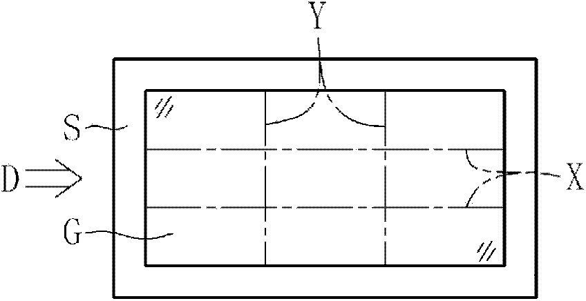
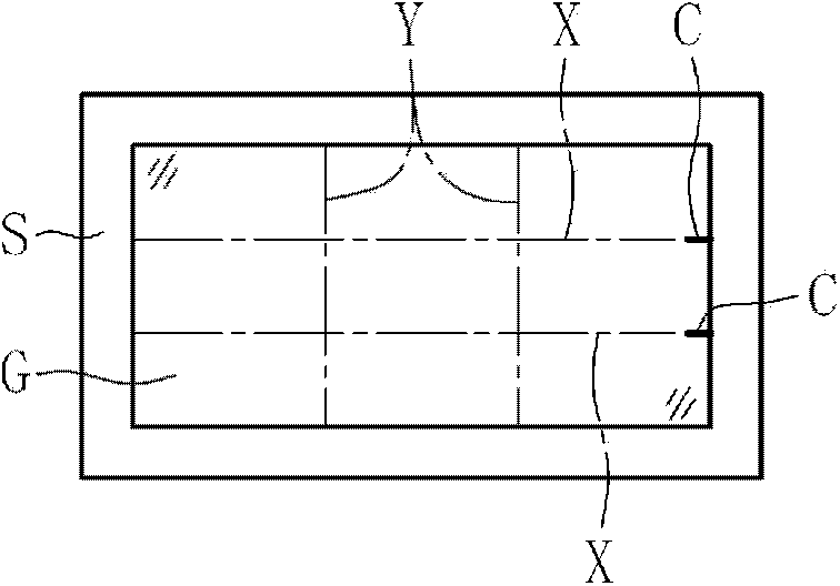
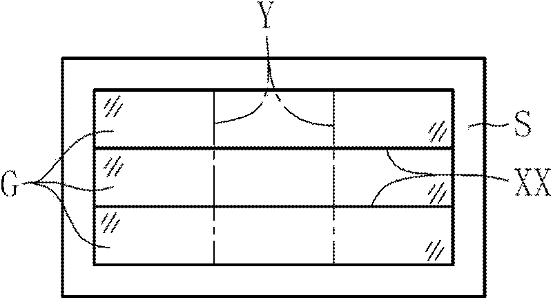
[0041] As the cutting and separating method of flat glass in the first embodiment of the present invention, such as Figure 1a~Figure 1h As shown, the following case is explained: the flat glass G is cut into 9 rectangular flat glass G using the laser cutting method, and the cut flat glasses G are separated from each other, and the unusable products of the flat glasses G are discarded part. It should be noted, Figure 1a~Figure 1g Is a top view, Figure 1h From Figure 1a The side view shown in the direction of arrow D is shown.
[0042] Such as Figure 1a As shown, in the first embodiment, the plate glass G cut by the laser cutting method is placed on a stretchable thin plate S (hereinafter, simply referred to as a thin plate S). As the material of the sheet S, various materials having stretchability represented by foamed polyethylene, foamed polystyrene, and foamed polypropylene can be used. In addition, it is preferable that the coefficient of friction between the glass plate G and the thin plate S be 1.0 or more.
[0043] Such as Figure 1b As shown, first, the two intersections of the two planned transverse cutting lines X of the plate glass G and one end surface of the plate glass G (one end surface in the direction orthogonal to the transverse cutting planned line X) are respectively engraved as Initial crack C at the base point of cutting. Each initial crack C can be carved by a mechanical method such as a wheel cutter, or by irradiating the sheet glass G with a short pulse laser. Next, the laser beam is irradiated and heated along the planned transverse cutting line X while being moved, and a refrigerant such as water mist is sprayed to the planned transverse cutting line X following the laser beam for cooling. As a result, thermal stress acts on the sheet glass G, and the initial crack C progresses along the planned transverse cutting line X by the thermal stress. Through such a cutting process, the plate glass G can be Figure 1c Cut in the manner shown, and form a transverse cut XX.
[0044] in Figure 1c In the state shown, as a separation process for the transverse cut portion XX of each plate glass G after cutting, such as Figure 1d As shown, when the sheet S is elongated in the vertical direction A with respect to the transverse cut portion XX, the sheet glass G after cutting is separated from each other with the elongation of the sheet S, so the cut surface of each sheet glass G They must be separated from each other. In this case, in the cutting process of the sheet glass G along the planned longitudinal cutting line Y performed after the separation process of the horizontal cut portion XX, it is preferable to engrave the initial crack C that becomes the base point of the cut in consideration The separation distance between the cut surfaces of the plate glass G after the cut is set to 1 mm or more.
[0045] Here, when cutting the plate glass G along the planned transverse cutting line X, a laser beam may be used to melt a part of the thin plate S to be welded to the plate glass G. In this case, the thin plate S and the plate glass G The contact surface becomes difficult to slide. Thereby, at the time of the separation process with respect to the horizontal cut part XX, the separation efficiency of the cut surfaces of each plate glass G after the cut accompanying the extension of the thin plate S can be improved. In addition, since the portion to be welded is limited, even in the case where the sheet S is welded to the sheet glass G manufactured as a glass substrate, it is possible to avoid impairing the function as a glass substrate as much as possible.
[0046] Then, like Figure 1e As shown, for each plate glass G separated at the transverse cutting portion XX, between two longitudinal cutting plan lines Y and one end surface of each plate glass G (one end surface in the direction orthogonal to the longitudinal cutting plan line Y) In the two intersections between the two, the initial crack C that becomes the base point of the cutting is carved. The initial crack C can also be carved by a known method.
[0047] in Figure 1e In the state shown, when going through the cutting process of laser cutting along the planned longitudinal cutting line Y, such as Figure 1f As shown, each sheet glass G is in a state of being cut along the planned longitudinal cutting line Y, and forms a longitudinal cutting portion YY. In the cutting process of cutting the plate glass G along the planned longitudinal cutting line Y, as described above, a part of the thin plate S may be melted by a laser beam to be welded to the plate glass G. In this case , It is possible to improve the separation efficiency of the cut surfaces of the plate glass G cut to be described later. In addition, since the portion to be welded is limited, even in the case where the sheet S is welded to the sheet glass G manufactured as a glass substrate, it is possible to avoid impairing the function as a glass substrate as much as possible.
[0048] in Figure 1f In the state shown, when Figure 1g As shown, when the sheet S is extended in the vertical direction B with respect to the longitudinal cut portion YY, the sheet glass G after cutting is separated from each other with the elongation of the sheet S, so the cut surfaces of each sheet glass G must also be mutually Separated from each other.
[0049] Such as Figure 1g As shown, when all the flat glasses G are separated from each other, in order to transfer the cut flat glasses G to the subsequent process and pick them up from the sheet S, the collision between the cut surfaces can also be avoided in advance ,slide. Therefore, it is possible to prevent the occurrence of scratches and cracks in the cut surface, and to appropriately eliminate important factors that cause the quality of the sheet glass G to decrease.
[0050] In addition, after the completion of the above-mentioned steps, among the plurality of pieces of each plate glass G after cutting, for example, Figure 1d In the case where thick ears are formed at the 6 pieces of flat glass G at the two ends in the A direction and cannot be used as a product, etc., make the two ends of the thin plate S in the A direction as Figure 1h As shown is inclined with respect to the horizontal plane, 6 pieces of plate glass G are dropped from the thin plate S and discarded. Thereby, these sheet glass G can be discarded quickly.
[0051] Here, in the above-mentioned first embodiment, the cutting of the plate glass G along the planned transverse cutting line X is performed, and the cut surfaces of the cut plate glass G are separated from each other at the transverse cutting portion XX, and then the cutting is performed. The cutting of the plate glass G along the planned longitudinal cutting line Y separates the cut surfaces of the cut plate glass G from each other at the longitudinal cutting portion YY. Among them, the present invention is not limited to such a structure, for example, it may be as Figure 2a~Figure 2d As shown in the second embodiment of the present invention, as the cutting process ( Figure 2a~Figure 2c ) After cutting the plate glass G along the planned horizontal cutting line X and cutting the plate glass G along the planned vertical cutting line Y, as a separation step, the separation step and the vertical alignment of the transverse cut portion XX are performed The separation process of the cutting part YY, such as Figure 2d As shown, the thin plate is elongated in the direction T along the two diagonal lines of the thin plate S, so that the cut surfaces of each plate glass G after being cut are separated from each other. At this time, in fact, the process of separating the transverse cut part XX and the process of separating the longitudinal cut part YY can be carried out at the same time, or it can be carried out at a predetermined time interval. In the case of a predetermined time interval, it can also be carried out preferentially Any process. In addition, in the case where the separation step for the transverse cut portion XX and the separation step for the longitudinal cut portion YY are simultaneously performed, the operation efficiency of the separation step can be improved. It should be noted that, in the drawings for explaining the present embodiment, the same reference numerals are given to components having the same function or shape as the above-mentioned first embodiment, and repeated descriptions are omitted.
[0052] In addition, in the second embodiment described above, it is not necessary to separate the cut surfaces from each other after the cutting of the plate glass G along the planned transverse cutting line X, but it must be the plate glass used for the longitudinal cutting along the planned line Y. The initial crack C at the base point of the cutting of G is carved at the intersection of the planned horizontal dicing line X and the planned vertical dicing line Y. In the case of this second embodiment, between the cut surfaces of each sheet glass G after cutting, there is only a slight gap for engraving the initial crack C, so it is used for cutting along the planned longitudinal cutting line Y. The initial crack C at the base point of the cutting of the sheet glass G is preferably engraved by a short pulse laser or the like compared to a mechanical method such as a wheel cutter. In addition, before cutting the plate glass G along the planned horizontal cutting line X, an initial crack C may be provided at the intersection of the planned horizontal cutting line X and the planned vertical cutting line Y using a short pulse laser in advance.
[0053] In addition, in the above-mentioned first embodiment, after performing the separation process of the longitudinal cut portion YY ( Figure 1g The structure of discarding the part of the multiple pieces of flat glass G that cannot be used as products (in the first embodiment, six pieces of flat glass G), but it can also be used in the cross-cut part After the separation process of XX ( Figure 1d The structure of discarding the part that cannot be used as a product before cutting the plate glass G along the planned longitudinal cutting line Y. In addition, by inclining an arbitrary portion of the thin plate S with respect to the horizontal plane, it is possible to discard an arbitrary number of plate glass G. For example, by inclining the respective ends of the two diagonal lines of the thin plate S, it is possible to discard the four plate glasses G located at the corners of the plurality of plate glasses G after cutting.

PUM

no PUM

Description & Claims & Application Information

We can also present the details of the Description, Claims and Application information to help users get a comprehensive understanding of the technical details of the patent, such as background art, summary of invention, brief description of drawings, description of embodiments, and other original content. On the other hand, users can also determine the specific scope of protection of the technology through the list of claims; as well as understand the changes in the life cycle of the technology with the presentation of the patent timeline. Login to view more.

Similar technology patents

Portable polishing device for processing elevator accessory

PendingCN109015271Aavoid scratcheswell polished
Owner:苏州谊佳润机电制造有限公司

Flange position degree testing fixture

PendingCN113418428AQuick checkavoid scratches
Owner:TIANRUN IND TECH CO LTD

Piston ring clamping tool

ActiveCN107214663Aavoid scratchesImprove assembly quality and efficiency
Owner:ANHUI JIANGHUAI AUTOMOBILE GRP CORP LTD

New energy automobile charging buckled cover assembling equipment

PendingCN109128789AEasy to fix with screwsavoid scratches
Owner:无锡腾马精密机械有限公司

Bridge structure for power transmission and transformation facility wiring

InactiveCN104235507AEasy tool-less disassemblyavoid scratches
Owner:TBEA SHENYANG TRANSFORMER GRP CO LTD

Classification and recommendation of technical efficacy words

Why Eureka
Try Eureka