Cam follower device

A technology of cams and supporting walls, applied to valve devices, engine components, machines/engines, etc., can solve the problems of reduced durability and achieve the effects of manufacturing costs, weight reduction, and miniaturization

Inactive Publication Date: 2014-03-12
NSK LTD
View PDF9 Cites 6 Cited by
  • Summary
  • Abstract
  • Description
  • Claims
  • Application Information

AI Technical Summary

Problems solved by technology

As a result, the load is repeatedly applied to the portion where the radial load of the support shaft 9 (9a) is loaded, and there is a possibility that the durability may decrease.

Method used


Image

  • Cam follower device
  • Cam follower device
  • Cam follower device

Examples


Embodiment Construction

[0048] [First example of embodiment]

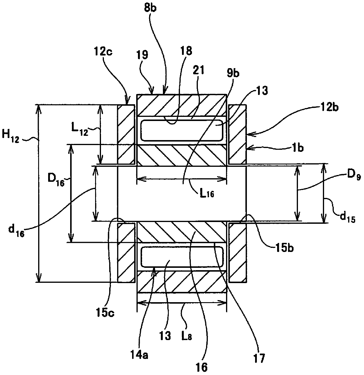
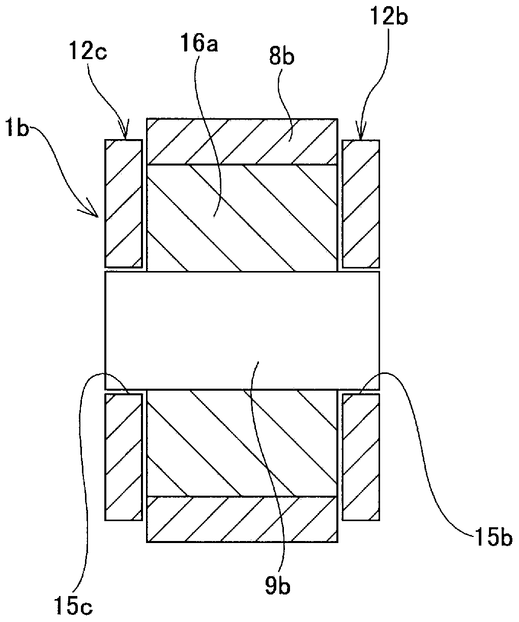
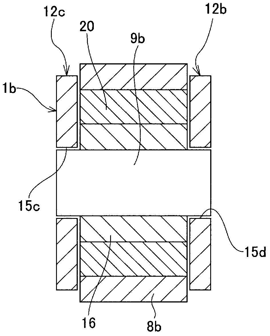
[0049] figure 1 The first example of the embodiment of the present invention is shown. Including this example, the cam follower of the present invention is characterized in that the support structure of the support shaft 9b to the support wall portions 12b, 12c, and that an inner ring equivalent member is provided between the support shaft 9b and the tappet roller 8b Namely the inner ring 16 . The structure of the cam follower other than the characteristic parts of the present invention and the state of assembly to the engine include Figure 12 to Figure 15 The shown structure is basically the same as the conventional structure, and the description thereof will be omitted or simplified, and the following description will focus on the characteristic parts of this example.

[0050] The cam follower of this example has a rocker arm 1b, a support shaft 9b, an inner ring 16 that is a member corresponding to the inner ring, a tappet roller ...


PUM


Abstract

Provided is a cam follower device having excellent durability, mountability, and design flexibility, and capable of achieving reductions in size, weight, and manufacturing cost. Both ends of a support shaft (3a) are relatively rotatably supported by support walls (12b, 12c) while being inserted through support holes (15b, 15c) of the support walls (12b, 12c). An inner ring (16) having an outer diameter (D16) larger than the inner diameter (d15) of the support holes (15b, 15c) is fitted onto the outer peripheral surface of an intermediate portion in the axial direction of the support shaft (9a) so as to be rotatable with the support shaft (9a). Further, a plurality of cylindrical rollers (13) are rollably disposed between an inner ring raceway (17) formed on the outer peripheral surface of the inner ring (16) and an outer ring raceway (18) formed on the inner peripheral surface of a tappet roller (8b) provided on the outer diameter side of the inner ring (16).

Description

technical field [0001] The present invention relates to a cam follower incorporated in a valve mechanism such as an engine for an automobile. Background technique [0002] As a valve actuator for transmitting the motion of a cam fixed to a camshaft that rotates synchronously with a crankshaft of an engine to a valve, the descriptions in JP-A-2006-183856 and JP-A-2005-326023 are widely used. cam followers. Figure 12 and Figure 13 A first example of the conventional structure of the cam follower described in Japanese Patent Application Laid-Open No. 2006-183856 is shown. The main body of the cam follower, that is, the rocker arm 1, is interspersed in its length direction ( Figure 12 The rocker shaft 3 in the shaft hole 2 formed in the middle part of the horizontal direction) is rotatably supported on the cylinder head (not shown) of the engine. In addition, the adjusting bolt 4 is screwed to the base end portion formed on the rocker arm 1 ( Figure 12 The threaded hole at...

Claims


Application Information

Patent Timeline
Patent Type & Authority Applications(China)
IPC IPC(8): F01L1/18
CPCF01L2105/02F01L1/18F01L1/14F01L1/181F01L2305/02F01L1/12
Inventor 野田浩史蜂须贺贤
Owner NSK LTD
Why Eureka
Try Eureka