Stress inspection device for knee-joint ligaments

A technology for stress inspection and knee joints, applied in gymnastics equipment, muscle training equipment, sports accessories, etc., can solve problems such as high stress, inconvenient work and life, and high cost, and achieve an increase in positive detection rate and accurate imaging diagnosis The effect of evidence and corroboration

Inactive Publication Date: 2014-03-19
孟辉
View PDF7 Cites 5 Cited by
  • Summary
  • Abstract
  • Description
  • Claims
  • Application Information

AI Technical Summary

Problems solved by technology

MRI and CT examinations can make a corresponding definite diagnosis, but MRI and CT are expensive and difficult for the injured to accept
However, conventional ordinary X-ray examinations often cannot meet the ideal diagnostic requirements. It is necessary to artificially stress all parts of the knee joint. Only by taking X-rays to check whether the knee joint space is widened can the diagnosis be made.
However, there is currently n

Method used


Image

  • Stress inspection device for knee-joint ligaments
  • Stress inspection device for knee-joint ligaments
  • Stress inspection device for knee-joint ligaments

Examples


Embodiment 1

[0025] Example 1 Knee Joint Patella Medial and Lateral Supporting Ligament Stress Checker

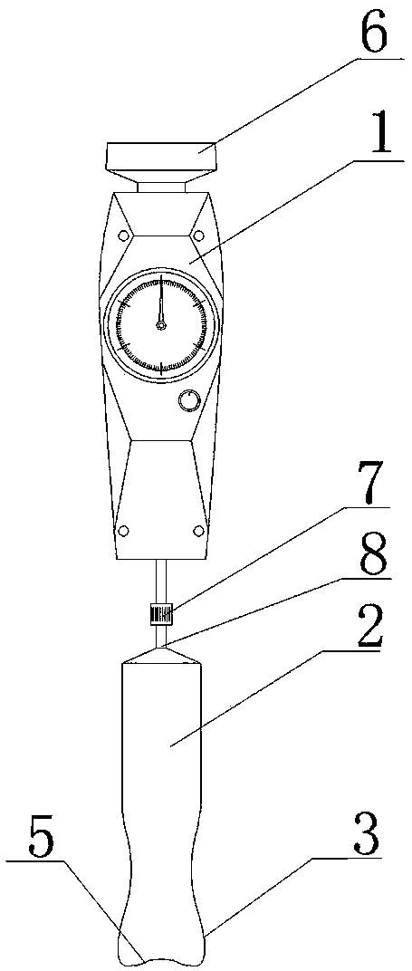
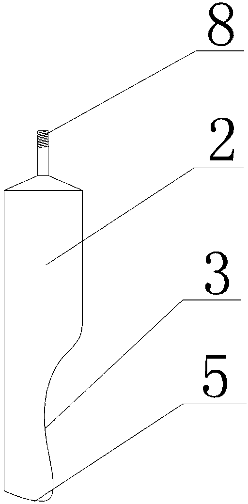
[0026] as attached figure 1 As shown, a knee joint patella medial and lateral supporting ligament stress tester includes a pressure gauge 1, a handle 6 and a limb contact part 2, the handle 6 is fixedly arranged on the top of the pressure gauge 1, and the lower part of the pressure gauge 1 is provided with Outer nut 7 , one end of limb contact part 2 is provided with patella side pressure plate 3 with arc-shaped groove 5 on the top, and the other end is provided with screw rod 8 matching outer nut 7 . as attached image 3 As shown, the structure of the arc-shaped groove 5 can match the structure of the lower border of the patella, so as to achieve the effect of lateral pressure on the patella.

[0027] When checking whether the knee joint patellar medial supporting ligament is damaged, the patient is allowed to sit on the radiography bed, and the legs are straightened, and then the pa...

Embodiment 2

[0029] Embodiment 2 Knee joint cruciate ligament, lateral collateral ligament stress checker

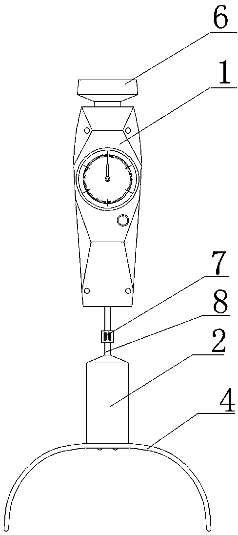
[0030] as attached figure 2 As shown, a knee cruciate ligament and collateral ligament stress tester includes a pressure gauge 1, a handle 6 and a limb contact part 2, the handle 6 is fixedly arranged on the top of the pressure gauge 1, and the lower part of the pressure gauge 1 is arranged There is an outer nut 7, one end of the limb contact part 2 is provided with a U-shaped femoral shin plate 4, and the other end is provided with a screw rod 8 matching the outer nut 7. Optional can be used together with the body contact, as attached Figure 4 As shown, the limb fixation belt includes a belt body 21, a fixing card 22, a handshake 23 and an adjustment member 24. The fixing card 22 is fixedly arranged on one end of the belt body 21, and the adjustment member 24 and the handshake 23 are fixedly arranged on the belt. Body 21.

[0031] When checking whether the anterior fork ligamen...


PUM


Abstract

The invention relates to a stress inspection device for knee-joint ligaments. The stress inspection device comprises a pressure measurement meter and a bodily contact component connected with the pressure measurement meter, and a patella side pressing plate or a thigh shin pressing plate is fixedly arranged at one end of the bodily contact component. According to the stress inspection device, the positive rate is greatly improved when damage to the knee-joint ligaments is inspected, the objective stress can be provided, damage to a patient can be avoided, the stress inspection device is convenient to use, economical and practical, and convenient, effective and accurate imaging diagnostic basis and evidences are provided for inspecting and treating the damage to the knee-joint ligaments of the patient.

Description

technical field [0001] The invention relates to a medical auxiliary device, in particular to a knee joint ligament stress tester, which belongs to the technical field of orthopedic surgery. Background technique [0002] As we all know, the knee ligament is an important structure to ensure the normal movement function of the knee joint. Knee ligament injury is a common and frequently-occurring disease. If not treated properly, it can lead to joint instability and affect joint function. At present, there are various deficiencies in the examination and diagnosis of knee ligaments. MRI and CT examinations can make a corresponding definite diagnosis, but MRI and CT are expensive and difficult for the injured to accept. However, routine ordinary X-ray examinations often cannot meet the ideal diagnostic requirements. It is necessary to artificially stress all parts of the knee joint. Only by taking X-rays to check whether the knee joint space is widened can the diagnosis be made....

Claims


Application Information

Patent Timeline
IPC IPC(8): A61B5/22
Inventor 孟辉于宝海郭哲吴文娟石静袁玉玲洪革苏宏远张祖卓
Owner 孟辉
Why Eureka
Try Eureka