
Turning tool for welding

A technology for welding turning tools and cutter heads, which is applied to lathe tools, turning equipment, tool holder accessories, etc. It can solve the problems of insufficient chip removal speed and difficulty in chip removal, and achieve chip removal The effect of fast speed and reducing the difficulty of processing

Inactive Publication Date: 2014-03-19
JIANGYIN SAITE PRECISION TOOL
View PDF0 Cites 2 Cited by
  • Summary
  • Abstract
  • Description
  • Claims
  • Application Information

AI Technical Summary

Problems solved by technology

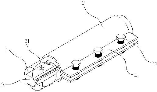
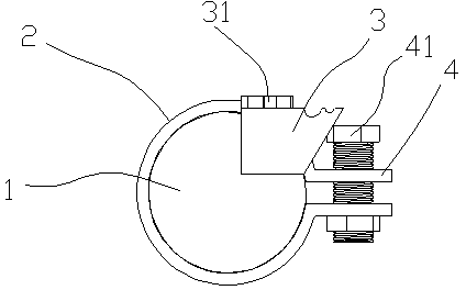
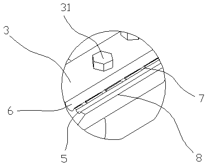
[0004] In order to solve the problem that the chip removal speed of the chip removal groove is not enough and the chip removal speed of the chip removal groove is not enough at present, the present invention provides a welding turning tool, which includes a tool holder 1, a tool holder 2 and a The cutter head 3, the cutter cover 2 is set on the cutter bar 1, the cutter head 3 is fixed on the end of the cutter bar 1, the blade 8 side of the cutter head 3 is sequentially opened with the first A chip removal groove 5 and a second chip removal groove 6, the first chip removal groove 5 and the second chip removal groove 6 communicate through a number of notches 7, wherein the width of the first chip removal groove 5 is less than The width of the second flute 6

Method used


Image

  • Turning tool for welding
  • Turning tool for welding
  • Turning tool for welding

Examples


Embodiment Construction

[0013] All features disclosed in this specification, or steps in all methods or processes disclosed, may be combined in any manner, except for mutually exclusive features and / or steps.

[0014] Any feature disclosed in this specification, unless specifically stated, can be replaced by other alternative features that are equivalent or have similar purposes. That is, unless expressly stated otherwise, each feature is one example only of a series of equivalent or similar features.

[0015] Such as figure 1 and figure 2 The shown welding turning tool comprises a tool holder 1, a cutter holder 2 and a cutter head 3, the cutter holder 2 is set on the cutter holder 1, and the cutter head 3 is fixed on the end of the cutter holder 1, and the cutter head 3 is After the chip removal groove is processed, it is fixed on the cutter bar 1 by two bolts 31, and the connection line of the two bolts 31 is not parallel to the axis of the cutter head 3, and the chip removal groove on the cutte...


PUM


Abstract

The invention discloses a turning tool for welding. The turning tool for welding comprises a tool bar (1), a tool sleeve (2) and a tool bit (3), wherein the tool bar (1) is sleeved with the tool sleeve (2), the tool bit (3) is fixed to the end of the tool bar (1), the side, where a blade (8) is located, of the tool bit (3) is provided with a first chip discharge groove (5) and a second chip discharge groove (6) in sequence in the axis direction of the tool bit (3), the first chip discharge groove (5) and the second chip discharge groove (6) are communicated with each other through a plurality of groove openings (7), and the width of the first chip discharge groove (5) is smaller than that of the second chip discharge groove (6). According to the turning tool for welding, the chip discharge grooves are convenient to machine, and the chip discharge speed is high.

Description

technical field [0001] The invention relates to a cutting tool, in particular to a welding turning tool. Background technique [0002] At present, turning tools in the society are mainly divided into welding turning tools and machine clip turning tools. The so-called welded turning tool is to open a knife slot on the carbon steel tool holder according to the geometric angle requirements of the tool, weld the cemented carbide blade in the knife slot with solder, and use the turning tool after sharpening according to the selected geometric parameters. . But there is following shortcoming in this welding turning tool: [0003] When workers use turning tools to turn workpieces, they must grind out flutes on the tool head, which obviously increases the workload of workers and reduces production efficiency. It is difficult for new workers who are inexperienced or not careful to grind out qualified turning tool. However, due to the complicated process of grinding the chip flute...

Claims


Application Information

Patent Timeline
Patent Type & Authority Applications(China)
IPC IPC(8): B23B27/00
CPCB23B27/18
Inventor 朱源陆少峰
Owner JIANGYIN SAITE PRECISION TOOL
Learn More