Supercharge Your Innovation With Domain-Expert AI Agents!

Oil pump shaft detecting and positioning mechanism

A technology of positioning mechanism and oil pump shaft, which is applied in the direction of measuring device, instrument, workpiece clamping device, etc., and can solve the problem of inability to detect the oil pump shaft, etc.

Inactive Publication Date: 2014-03-19
CHONGQING JIANWEI MACHINERY
View PDF0 Cites 0 Cited by
  • Summary
  • Abstract
  • Description
  • Claims
  • Application Information

AI Technical Summary

Problems solved by technology

However, the current positioning mechanism of the oil pump shaft cannot detect whether the processing of the oil pump shaft is qualified

Method used


Image

  • Oil pump shaft detecting and positioning mechanism
  • Oil pump shaft detecting and positioning mechanism

Examples


Embodiment Construction

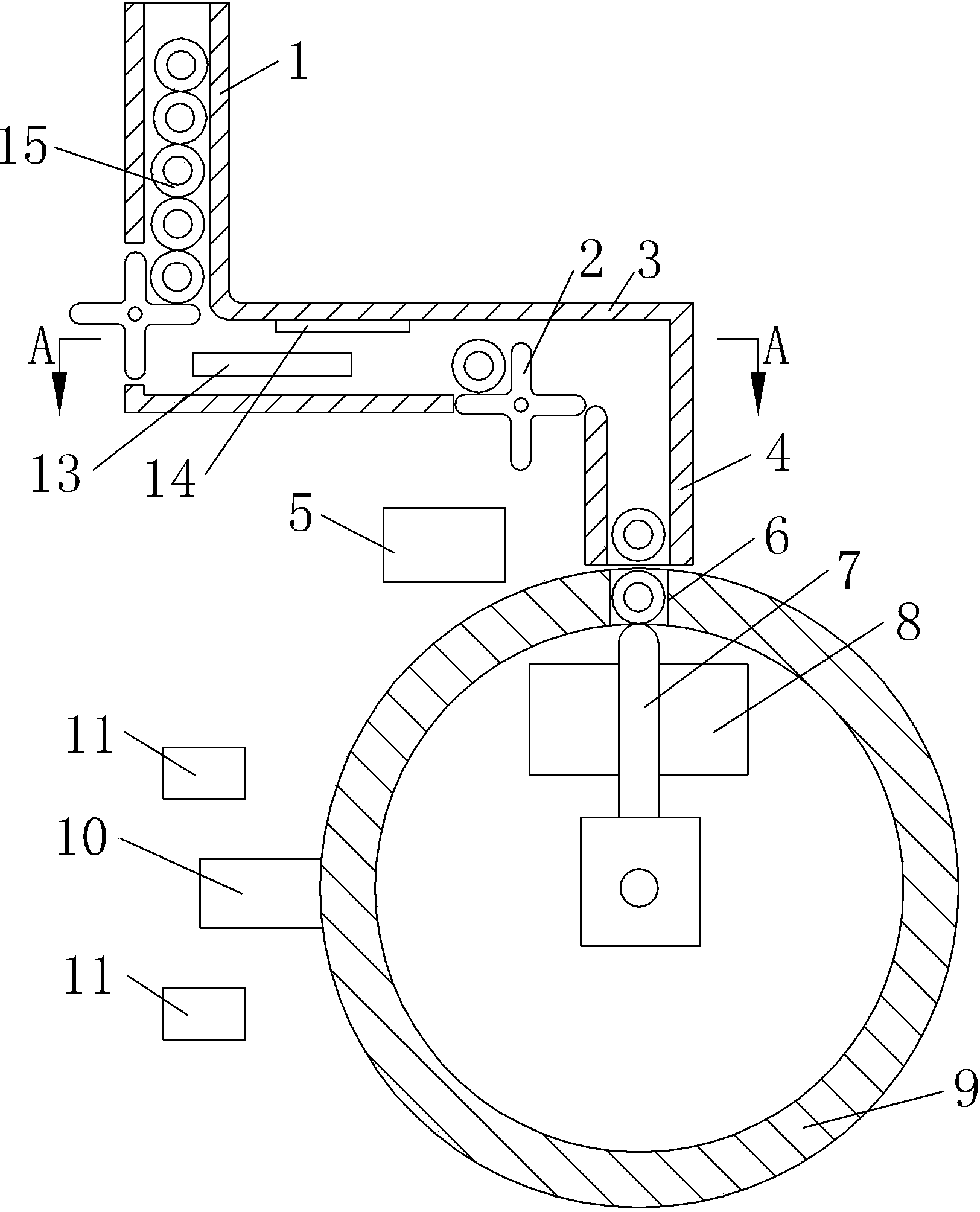
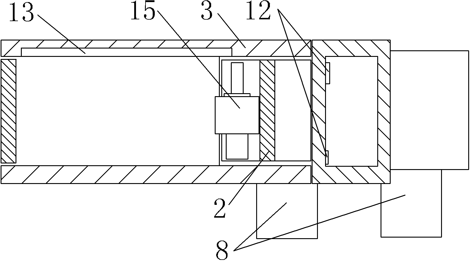
[0009] The reference signs in the drawings of the specification include: input chute 1, cross-shaped stopper 2, detection pipe 3, feed pipe 4, waste chute 5, notch 6, support pin 7, output chute 8, positioning drum 9. Control handle 10, solenoid valve 11, orientation detector 12, cylindricity detector 13, shaft runout detector 14, oil pump shaft 15.

[0010] Below in conjunction with accompanying drawing and embodiment technical solution of the present invention is described in further detail:

[0011] For the convenience of description, the "Up", "Down", "Left" and "Right" referred to below are respectively related to the attached figure 1 The up, down, left and right directions are the same, but it does not limit the structure of the present invention.

[0012] Such as figure 1 and figure 2 As shown, the oil pump shaft detection and positioning mechanism of an embodiment of the present invention includes an input chute 1, an output chute 8, a solenoid valve 11, a detecti...


PUM


Abstract

The invention discloses a machine tool part, and particularly relates to an oil pump shaft detecting and positioning mechanism which comprises an input sliding chute, an output sliding chute, electromagnetic valves, a detecting pipeline, a feeding pipe, a positioning drum wheel and a supporting pin, the center of the positioning drum wheel is hinged to a supporting arm, the side wall of the positioning drum wheel is provided with a notch and a control handle, the side wall of the notch is fixedly connected with a direction detector, the supporting pin fixedly connected with the supporting arm is arranged below the notch, two sides of the supporting pin are fixedly connected with the output sliding chute, two sides of the control handle are respectively provided with one electromagnetic valve, a cylindricity and shaft runout detector is arranged on the inner wall of the detecting pipeline, two ends of the detecting pipeline are communicated and fixedly connected with the input sliding chute and the feeding pipe respectively, a cross stopper is hinged onto the side wall of the input sliding chute close to one end of the detecting pipeline, another cross stopper is hinged to the lower portion of the detecting pipeline close to one end of the feeding pipe, and the feeding pipe is positioned above the positioning drum wheel and can be communicated with the notch. The oil pump shaft detecting and positioning mechanism can be used for detecting and positioning an oil pump shaft, and is simple in structure and high in practicability.

Description

technical field [0001] The invention relates to a mechanism for processing an oil pump shaft, in particular to a detection and positioning mechanism for an oil pump shaft. Background technique [0002] During the machining process of the oil pump shaft, it is necessary to detect and locate the cylindricity and runout of the oil pump shaft. But the current positioning mechanism of the oil pump shaft cannot detect whether the processing of the oil pump shaft is qualified. Contents of the invention [0003] The technical problem to be solved by the present invention is to provide a mechanism capable of detecting and locating the oil pump shaft, which has a simple structure and strong practicability. [0004] In order to solve the above-mentioned technical problems, the present invention provides an oil pump shaft detection and positioning mechanism, which includes an input chute, an output chute and a solenoid valve, and also includes a detection pipeline, a feed pipe, a pos...

Claims


Application Information

Patent Timeline
Patent Type & Authority Applications(China)
IPC IPC(8): B25B11/00
CPCB25B11/00G01B21/00G01B21/20
Inventor 江伟
Owner CHONGQING JIANWEI MACHINERY
Features
  • R&D
  • Intellectual Property
  • Life Sciences
  • Materials
  • Tech Scout
  • Unparalleled Data Quality
  • Higher Quality Content
  • 60% Fewer Hallucinations
Learn More