Laser beam parallelism adjustment system and laser beam parallelism adjustment method for road surface deflection measurement

A road surface deflection and adjustment system technology, applied in roads, roads, road repairs, etc., can solve problems such as complex operation, high cost, and poor practicability

Active Publication Date: 2014-03-19
BEIJING LUXING NEW ROAD TECH
View PDF6 Cites 12 Cited by
  • Summary
  • Abstract
  • Description
  • Claims
  • Application Information

AI Technical Summary

Problems solved by technology

Although this method is theoretically feasible, in the actual calibration process, in order to ensure the rigidity of the 4000mm long calibration platform, its structure must be very heavy, and a high-precision optical camera and speed measurement system must be used. Poor practicability and high cost during use
[0006] As mentioned above, the first calibration method is the calibration of the transfer nature, which requires the construction of a test road and the need to embed an acceleration sensor on the road, which will cause a lot of inconvenience to the subsequent calibration and maintenance.
[0007] Another method by moving the calibration platform at the bottom of the laser velocimeter is theoretically feasible, but in the actual calibration process, in order to determine whether the laser beam of the laser velocimeter is parallel, a dedicated scale plate and the same number as the laser velocimeter are required. high-end cameras, high cost and complicated operation
In addition, the calibration platform simulates the speed of the vehicle, and it is difficult to ensure that the direction of the movement speed of the calibration platform is parallel to the direction of the speed of the test vehicle. It must be very difficult to implement in practice.
Moreover, in order to ensure the rigidity of the 4000mm long calibration platform, its structure must be heavy and practicable

Method used


Image

  • Laser beam parallelism adjustment system and laser beam parallelism adjustment method for road surface deflection measurement
  • Laser beam parallelism adjustment system and laser beam parallelism adjustment method for road surface deflection measurement
  • Laser beam parallelism adjustment system and laser beam parallelism adjustment method for road surface deflection measurement

Examples


Embodiment Construction

[0045] The technical solutions of the present invention will be further described below in conjunction with the accompanying drawings and through specific implementation methods.

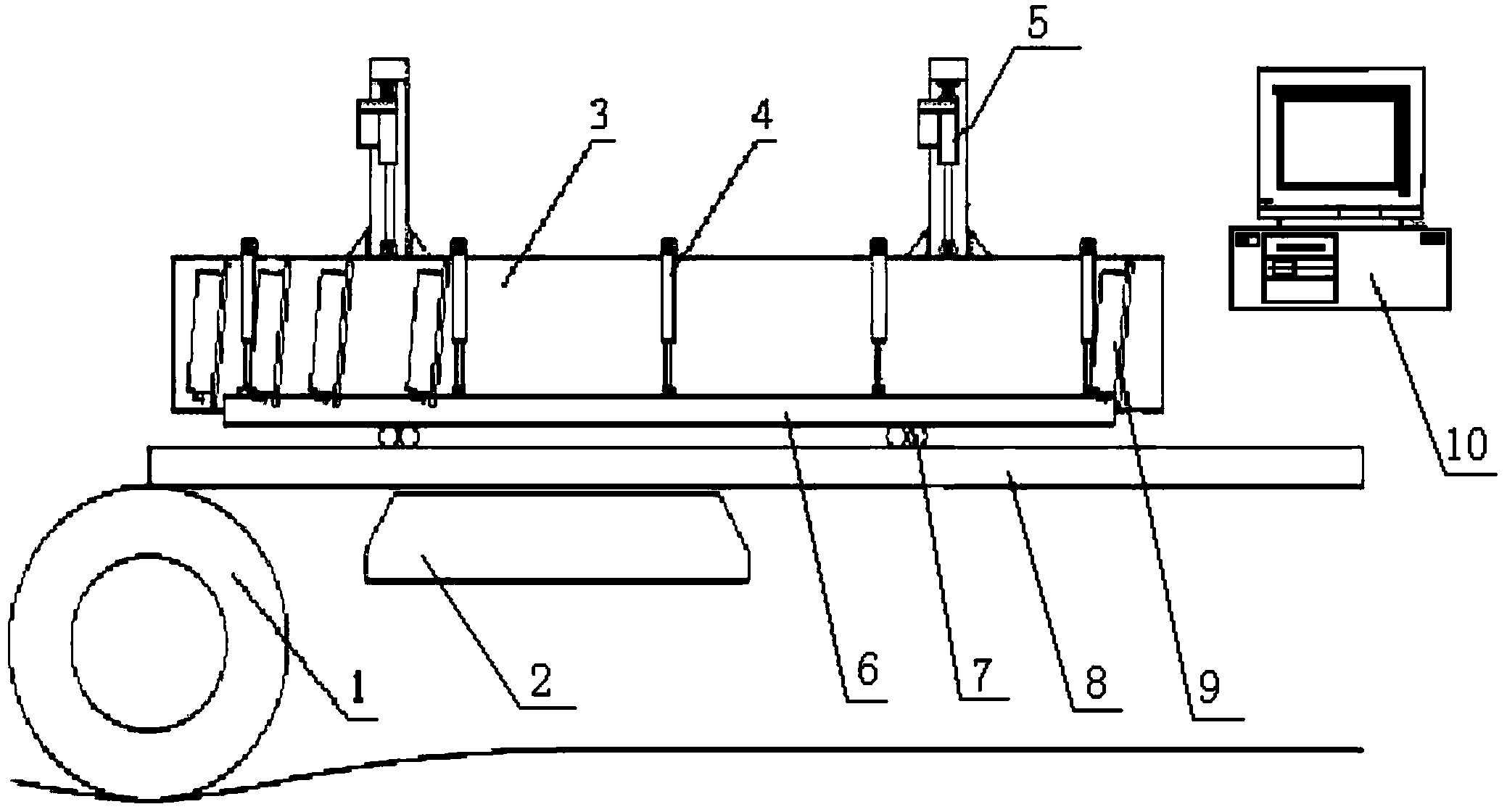
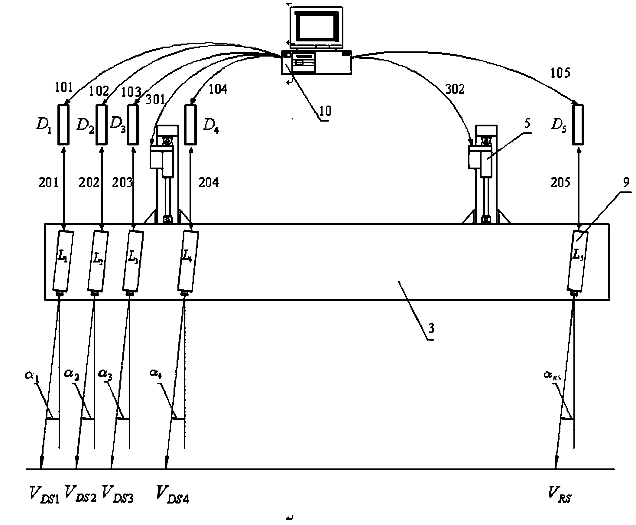
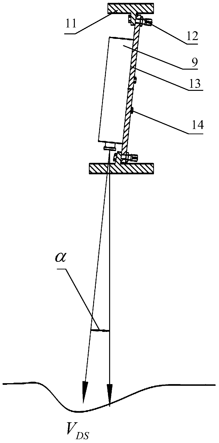
[0046] This scheme mainly uses a set of servo control device to drive the laser test common beam equipped with several laser velocimeters to move vertically. By comparing the vertical movement speed value of the laser test common beam with the speed value of each laser velocimeter, it can be determined Whether the laser beams of each laser velocimeter are parallel. And when the deflection test vehicle is running at normal speed, the actual installation angle value of the reference laser speedometer can be obtained quickly and accurately.

[0047] This system mainly includes laser testing common beam, mobile steel beam frame, guide rail platform, servo control device, signal acquisition system, shock absorption system, load wheel and counterweight, etc. By setting the running speed of the electric p...


PUM


Abstract

The invention relates to the field of road surface deflection measurement, and in particular relates to a laser beam parallelism adjustment system and a laser beam parallelism adjustment method for the road surface deflection measurement. The system comprises a laser test common beam which is arranged on a movable steel beam frame; the movable steel beam frame is arranged on a linear guide rail platform; the laser test common beam is provided with more than three laser velocimeters; each laser velocimeter is connected with a controller by a speed signal acquisition device; and the system also comprises a servo control device used for controlling the laser test common beam to make vertical uniform motion. The system can be used for judging whether laser beams of the laser velocimeters are parallel or not. The system also comprises a laser beam included angle adjustment device, so that the included angles between the laser velocimeters and the vertical direction can be adjusted by the laser beam included angle adjustment device. After the system is adopted, the actual installation angle value of a reference laser velocimeter can be rapidly and accurately obtained when a deflection test vehicle travels at the normal speed.

Description

technical field [0001] The invention relates to the field of road surface deflection measurement, in particular to a laser beam parallelism adjustment system and method for road surface deflection measurement. Background technique [0002] In the existing technology, most road deflection rapid detection equipment in the highway industry is based on the Beckman beam measurement method, which directly measures the displacement of the road surface subsidence under the standard load (10t) to calculate the deflection value index of the road surface , The testing speed of the testing equipment is generally 4-5km / h. Therefore, the improvement of the testing efficiency of the pavement deflection testing equipment is restricted. With the continuous development of modern science and technology, especially the continuous improvement of Doppler laser speed measurement technology, this technology has been introduced into the detection of road deflection. In foreign countries, the Puler...

Claims


Application Information

Patent Timeline
Patent Type & Authority Applications(China)
IPC IPC(8): E01C23/01
Inventor 吴智山侯君辉李孝兵孙成来呼六福
Owner BEIJING LUXING NEW ROAD TECH
Why Eureka
Try Eureka