High-energy laser homogenizing cavity attenuator

A high-energy laser and homogenizing cavity technology, applied in the field of array attenuators, can solve the problems of small size of integrating sphere, limited laser incident angle, etc., achieve large contact thermal resistance, reduce the difficulty of calibration, and reduce the effect of thermal influence

A high-energy laser and homogenizing cavity technology, applied in the field of array attenuators, can solve the problems of small size of integrating sphere, limited laser incident angle, etc., achieve large contact thermal resistance, reduce the difficulty of calibration, and reduce the effect of thermal influence

CN103644967AActive Publication Date: 2014-03-19NORTHWEST INST OF NUCLEAR TECH

Image

  • High-energy laser homogenizing cavity attenuator
  • High-energy laser homogenizing cavity attenuator
  • High-energy laser homogenizing cavity attenuator

Examples


Embodiment Construction

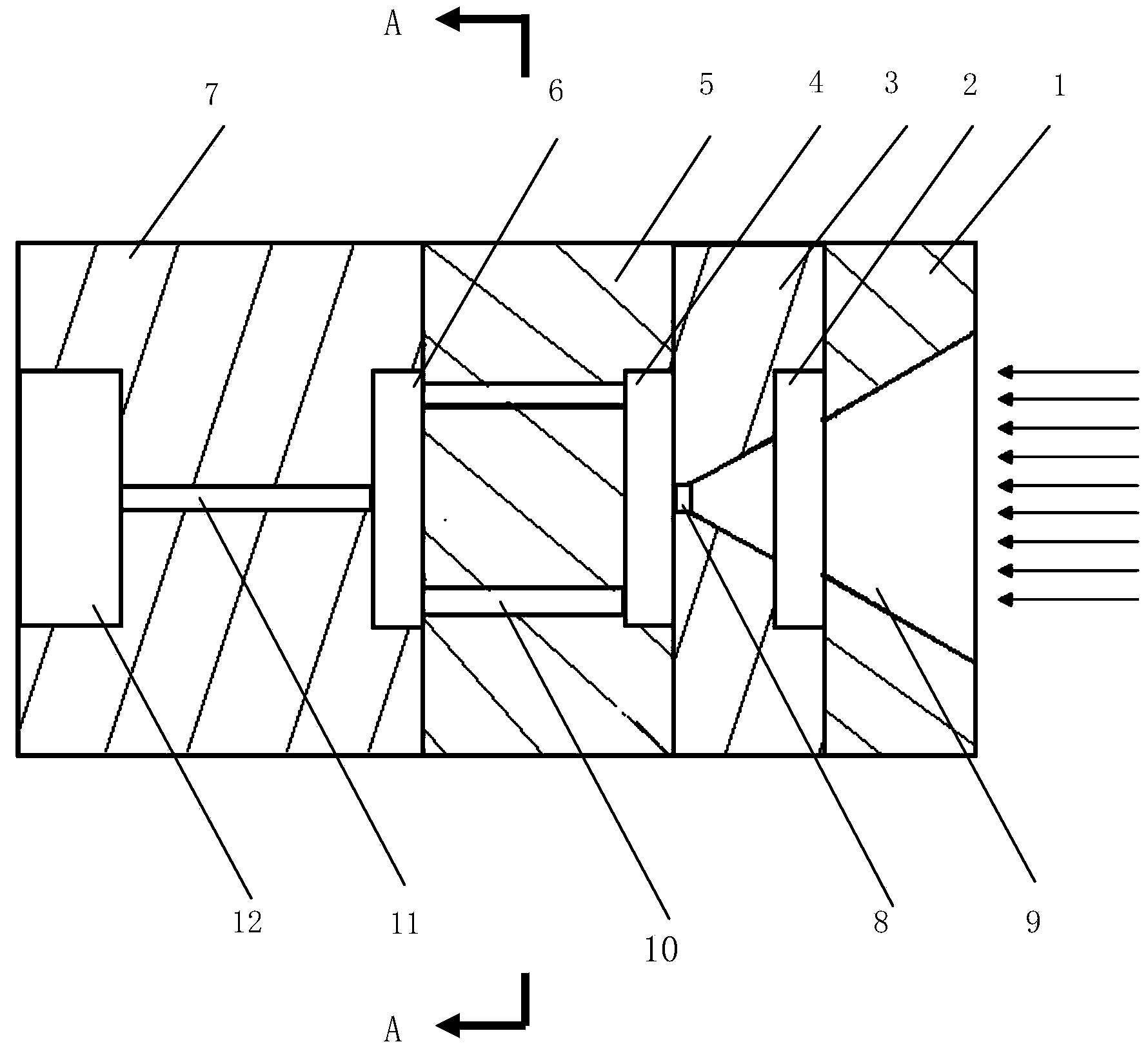
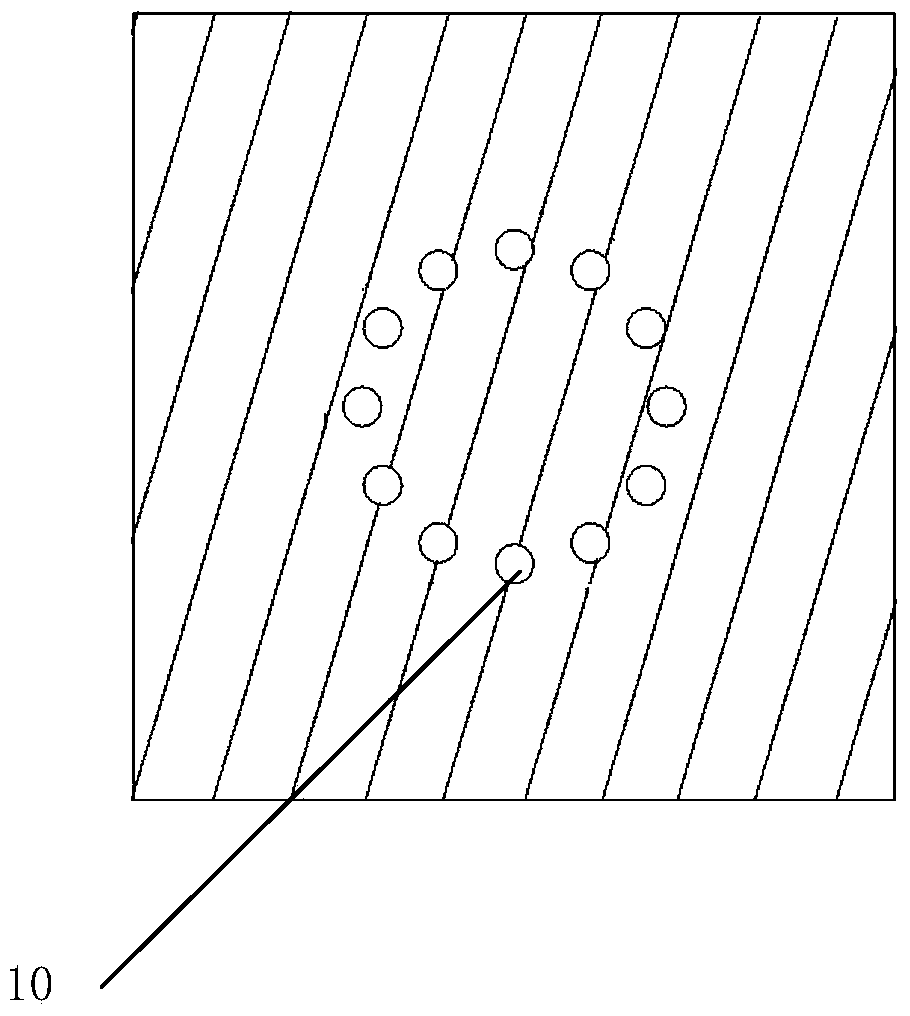
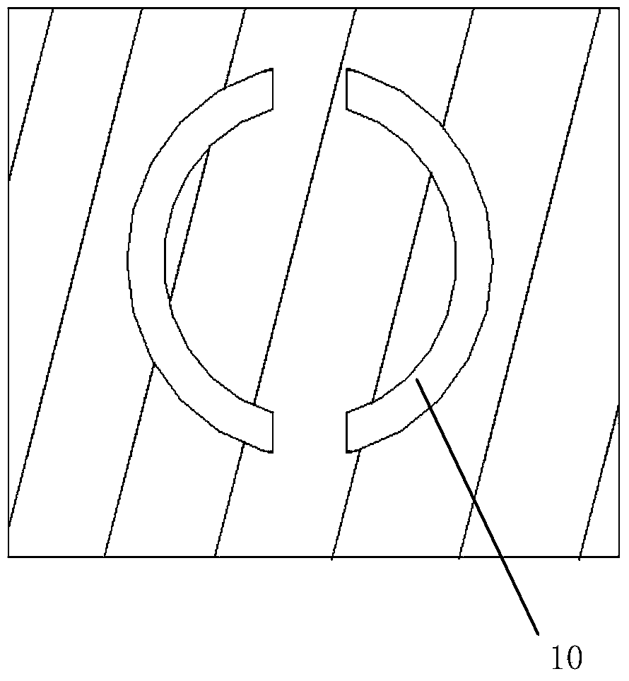
[0033] Such as figure 1 As shown, the high-energy laser homogenization cavity attenuator includes a front panel 1 , a small hole sampling panel 3 , an attenuation panel 5 and an output panel 7 arranged in sequence along the incident laser direction. After the front panel 1 and the small hole sampling plate 3 are laminated, a large-angle sampling cone 9 is processed on it, and the opening end of the large-angle sampling cone 9 is arranged on the front panel 2, facing the laser incident direction, and the tail end Set the inside of the small hole sampling plate 3, and communicate with the light-through straight hole 8 coaxially arranged at the rear end of the small hole sampling plate 3; the front end of the attenuation plate 5 is provided with a homogenization cavity 4, the thickness of the cavity is about 1 mm, and the diameter is about 5 mm. The cavity of the homogenization cavity is processed into a diffuse reflection surface; a light transmission channel 10 is arranged betw...


PUM


Abstract

The invention discloses a high-energy laser homogenizing cavity attenuator which comprises a front panel, a small-hole sample plate, an attenuation plate, an output panel and a plurality of scattering attenuation units. Each attenuation unit includes a large-angle sampling taper hole arranged on the small-hole sample plate, a homogenizing cavity and a light transmission channel which are arranged on the attenuation plate, and a homogenizing cavity and a laser output hole which are arranged on the output panel, wherein the light transmission channel is of a circular symmetric structure, which enables the angle characteristic of the attenuator to have circular symmetry. The attenuator has a multi-layer plate structure, which can effectively reduce the influence of high temperature generated due to long-time irradiation of high-energy laser on the front panel to a subsequent measurement unit. According to the attenuator of the invention, laser is output from the output hole after being homogenized for multiple times, substantial attenuation of the laser power density is achieved, and the attenuator has better attenuation angle characteristics.

Description

technical field [0001] The invention relates to an attenuator for high-energy laser beams, in particular to an array attenuator for measuring high-energy laser beams. Background technique [0002] In the measurement of high-energy laser parameters, it is necessary to obtain the spatiotemporal distribution of laser light intensity. Since the laser power density at the test position is generally high, reasonable attenuation is required to detect it with a photodetector array arranged in an area array. [0003] At present, the commonly used optical attenuation methods mainly include the filter attenuation method and the integrating sphere attenuation method, that is, an optical attenuator is added in front of each detector to attenuate the power of the laser to within the detectable range of the detector. Because the attenuation coefficient of the filter is difficult to accurately calibrate when it is attenuated by a large multiple, and the power meter for calibration is high, ...

Claims


Application Information

Patent Timeline
19 Mar 2014
Publication
CN103644967A
IPC
G01J1/04
Inventors
吴勇; 杨鹏翎