Novel integrated optical waveguide device for fiber-optic gyroscope

A technology integrating optical waveguide and fiber optic gyroscope, applied in Sagnac effect gyroscopes, optics, instruments, etc., can solve the problems of large energy loss, poor consistency of acousto-optic switches, large size, etc., and achieve high pulse modulation bandwidth, The effect of high temperature uniformity and design symmetry

Active Publication Date: 2014-03-19
THE 41ST INST OF CHINA ELECTRONICS TECH GRP
View PDF5 Cites 10 Cited by
  • Summary
  • Abstract
  • Description
  • Claims
  • Application Information

AI Technical Summary

Problems solved by technology

[0004] (1) The coupling ratio of the two couplers needs to be reasonably designed according to the number of times the light propagates in the fiber ring, and this process is difficult to realize;
[0005] (2) The transmission characteristics of the two couplers are poorly consistent in the full temperature environment (-40°C ~ 60°C), and the non-reciprocity introduced by this is very large and difficult to eliminate;
[0006] (3) In the process of optical transmission, due to the existence of the coupler, the energy loss is relatively large, which increases the difficulty of processing the subsequent optical signal;
[0008] (1) The transmission characteristics of the two acousto-optic switches are very poorly consistent in a full-temperature environment (-40°C to 60°C), and the non-reciprocity introduced by this is very large and difficult to eliminate;
[0009] (2) The response speed cannot reach the μs level, and it can only be assembled in separate parts, and the size is large, which is not suitable for the use of the overall fiber optic gyroscope

Method used


Image

  • Novel integrated optical waveguide device for fiber-optic gyroscope
  • Novel integrated optical waveguide device for fiber-optic gyroscope
  • Novel integrated optical waveguide device for fiber-optic gyroscope

Examples


Embodiment 1

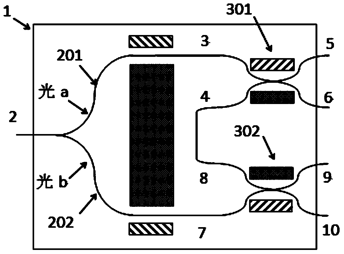
[0028] Such as figure 1 As shown, the present invention provides a novel design of an integrated optical waveguide device for a fiber optic gyroscope, which integrates functions such as polarization, beam splitting / combining, phase modulation, switch control, and multiple cycles in an optical fiber ring. It is mainly divided into three parts: lithium niobate optical chip 1, Y waveguide 2 and two integrated optical switches 301, 302, wherein Y waveguide 2 has chrome-gold electrodes 1 and ground on its two branches 201, 202 respectively, so as to realize Perform phase modulation, beam splitting, and beam combining functions on the beams in the branches; respectively make chrome-gold electrodes 2 and ground at the beam coupling parts of the optical switches 301 and 302, so as to select the beam flow direction in the optical switches and realize switch control and Multi-circulation function in fiber optic ring. The Y branch 201 is connected to the port 3 of the optical switch 301...

Embodiment 2

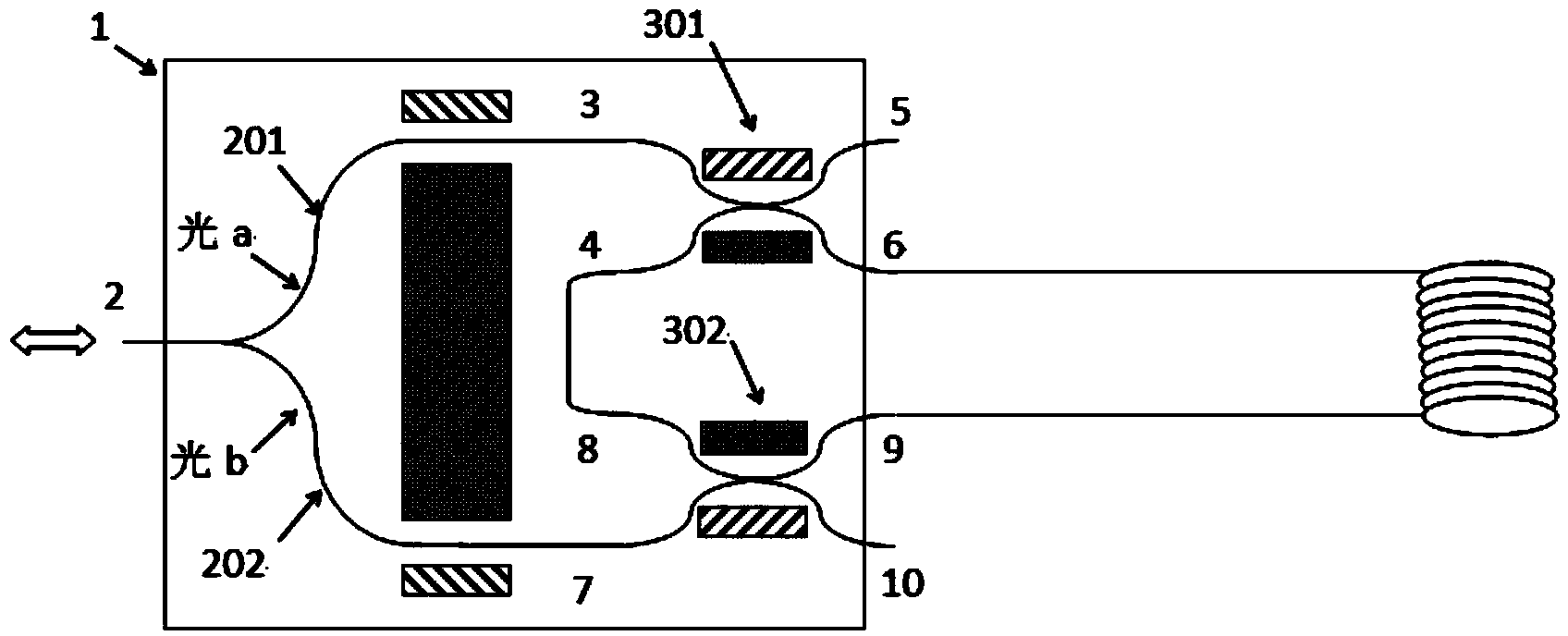
[0032] On the basis of the above examples, if figure 2 As shown, connect port 6 and port 9 to the two ports of the fiber ring, port 4 and port 8 are connected through an optical waveguide, assuming that the transit time of light in the fiber ring is τ, and the light propagates n cycles in the fiber ring, then the loading The pulse width on electrode 1 and electrode 2 is τ, and the repetition rate is The light from the light source is divided into two beams after passing through the Y waveguide 2. When the voltage signal is loaded on the electrodes 1 and 2, a beam of light a passes through the Y branch 201, the port 3 and the port 6 of the optical switch 301 and enters the optical fiber ring. Enter the optical switch 302 port 9 through the optical fiber ring, and at the same time, another beam b enters the optical fiber ring through the Y branch 202, port 7, and port 9 of the optical switch 302, and enters the optical switch 301 port 6 through the optical fiber ring. At this...

Embodiment 3

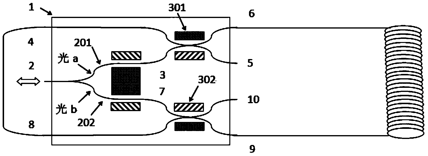
[0034] On the basis of the above embodiments, another embodiment is provided, such as image 3 As shown, the above-mentioned port 4 and port 8 are connected by a polarization-maintaining optical fiber.


PUM


Abstract

The invention provides a novel integrated optical waveguide device for a fiber-optic gyroscope. The integrated optical waveguide device comprises a Y waveguide, a first integrated optical switch and a second integrated optical switch, wherein first ports of the first and second optical switches are connected with a first branch and a second branch of the Y waveguide respectively; fourth ports of the first and second optical switches are connected with two ports of a fiber-optic ring respectively; the Y waveguide is used for polarizing and dividing wide-spectrum light emitted from a light source in the fiber-optic gyroscope into two beams of polarized light in uniform amplitude so as to realize phase modulation, beam splitting and beam combination of light beams; and the first and second optical witches are used for selecting transmission ports of the light beams and controlling transmission paths of the light beams. With the adoption of the scheme, the novel integrated optical waveguide device for the fiber-optic gyroscope is designed on a same base material by adopting an integrated structure, the Y waveguide and the optical switches are symmetric and compact in design, and the optical waveguide device is very high in temperature consistence.

Description

technical field [0001] The invention belongs to the technical field of optical fiber sensing and measurement, and in particular relates to a novel integrated optical waveguide device for an optical fiber gyroscope. Background technique [0002] As the key sensor of the new generation of high-precision inertial navigation system, fiber optic gyroscope has attracted much attention because of its high anti-interference and anti-shock capabilities. It has been used in military fields such as aerospace, ships, and missiles. The current way to increase the accuracy of fiber optic gyroscopes is to increase the length of the fiber optic ring, but the dynamic range of the gyroscope is greatly limited, and the bandwidth is also reduced. And with the increase of the length of the fiber ring, the winding process of the fiber ring becomes more complicated and more sensitive to the environment such as temperature and vibration, but the accuracy does not increase significantly with the in...

Claims


Application Information

Patent Timeline
Patent Type & Authority Applications(China)
IPC IPC(8): G02F1/313G02F1/035G01C19/72
Inventor 郑光金李国超韩正英赵耀高业胜
Owner THE 41ST INST OF CHINA ELECTRONICS TECH GRP
Why Eureka
Try Eureka