A wafer defect detecting method

A defect detection and detection method technology, applied in semiconductor/solid-state device testing/measurement, electrical components, circuits, etc., can solve the problems of low wafer defect detection efficiency, undetected, decreased process efficiency, etc., to improve defects Recognition rate and process efficiency, effective detection, low cost effect

Active Publication Date: 2014-03-19
SHANGHAI HUALI MICROELECTRONICS CORP
View PDF6 Cites 28 Cited by
  • Summary
  • Abstract
  • Description
  • Claims
  • Application Information

AI Technical Summary

Problems solved by technology

[0005] In the above defect detection method, due to known problems in the production process that do not require special attention, the number of defects in a specific area on the wafer is very high. If we follow the existing detection method and use a defect number threshold to judge Whether to perform subsequent processing on the wafer, each batch of wafers will meet this judgment and be required to undergo subsequent processing. In the case that this process problem does not require special control, it will cause low efficiency of wafer defect detection , or the defects that really need to be dealt with are not detected, resulting in a decrease in process efficiency and an increase in cost

Method used


Image

  • A wafer defect detecting method
  • A wafer defect detecting method
  • A wafer defect detecting method

Examples


Embodiment Construction

[0020] The specific embodiment of the present invention will be further described in detail below in conjunction with the accompanying drawings.

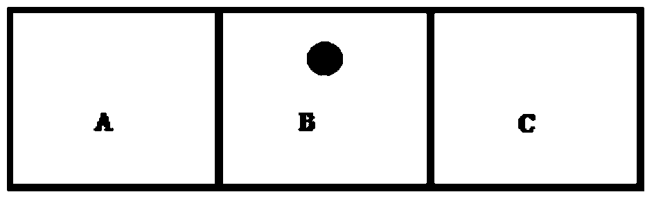
[0021] It should be noted that the wafer includes a plurality of chips, and dicing lines are provided between the chips. When the subsequent process is completed, the chips can be separated by cutting the wafer along the dicing lines.

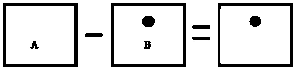
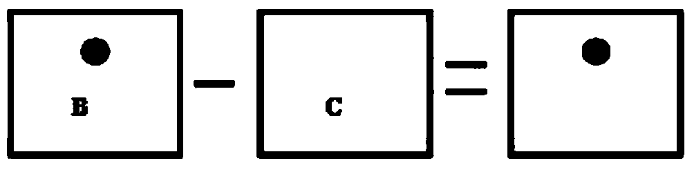
[0022] The detection of the wafer by the detection beam is used in combination with an industrial camera. The area on the wafer on which the detection beam is projected is observed by the industrial camera, and combined with certain image processing measures, through the identification and comparison of the gray features of the image, it can be Effectively detect defects in each chip area of ​​the wafer.

[0023] Such as image 3 As shown, the wafer defect detection method provided by an embodiment of the present invention includes the following steps:

[0024] Step S10 , moving the wafer one by on...


PUM


Abstract

The invention relates to a wafer defect detecting method comprising following steps: gradually moving a wafer in order to perform first defect detection on various chip regions of the wafer with a first scanning resolution; dividing the surface of the wafer into multiple detecting regions according to defect distribution information obtained from the first defect detection and setting a defect amount threshold value for each detecting region, wherein the defect amount threshold value is in positive correlation relation to the defect amount of a corresponding detecting region; gradually moving the wafer in order to perform second defect detection on various chip regions of the wafer with a second scanning resolution, wherein the second scanning resolution is less than the first scanning resolution; performing defect correction technology on the wafer if the defect amount of any detecting region exceeds a corresponding defect amount threshold value. The wafer defect detecting method increases the applicability of the wafer defect detecting method in actual technology, substantially increases defect recognition rate and technology efficiency. The wafer defect detecting method has high precision and low cost and is beneficial to popularization in industry field.

Description

technical field [0001] The invention relates to the field of semiconductor processing and manufacturing, and more specifically, to a wafer defect detection method. Background technique [0002] The advanced integrated circuit manufacturing process generally includes hundreds of steps, and a small error in any link will lead to the failure of the entire chip, especially as the critical size of the circuit continues to shrink, the requirements for process control become stricter, so In the production process, in order to find and solve problems in time, optical and electronic defect detection equipment are equipped to carry out online detection of products. [0003] The basic principle of optical and electronic defect detection is to collect the signals of several chips through the equipment, and convert the physical image on the chip into a data image that can be represented by different bright and dark gray scales. A method for detecting defects on a wafer in the prior art ...

Claims


Application Information

Patent Timeline
Patent Type & Authority Applications(China)
IPC IPC(8): H01L21/66
CPCH01L22/12H01L22/20
Inventor 倪棋梁范荣伟陈宏璘龙吟
Owner SHANGHAI HUALI MICROELECTRONICS CORP
Why Eureka
Try Eureka