Light-emitting diode (LED) switch constant-current driving circuit

A technology of constant current drive and LED module, which is applied in the direction of lamp circuit layout, electric light source, lighting device, etc., and can solve the problem of high application cost, low stability, incompatibility between LED drive circuit and thyristor dimmer and electronic transformer. Compatibility and other issues to achieve the effect of high stability and cost reduction

Inactive Publication Date: 2014-03-19
SHANGHAI LATRONIX TECH CORP
View PDF7 Cites 42 Cited by
  • Summary
  • Abstract
  • Description
  • Claims
  • Application Information

AI Technical Summary

Problems solved by technology

[0007] In view of the shortcomings of the prior art described above, the purpose of the present invention is to provide a constant current drive circuit for LED switches, which is used to solve t

Method used


Image

  • Light-emitting diode (LED) switch constant-current driving circuit
  • Light-emitting diode (LED) switch constant-current driving circuit
  • Light-emitting diode (LED) switch constant-current driving circuit

Examples


Embodiment Construction

[0064] Embodiments of the present invention are described below through specific examples, and those skilled in the art can easily understand other advantages and effects of the present invention from the content disclosed in this specification. The present invention can also be implemented or applied through other different specific implementation modes, and various modifications or changes can be made to the details in this specification based on different viewpoints and applications without departing from the spirit of the present invention.

[0065] see Figure 2 to Figure 14 . It should be noted that the diagrams provided in this embodiment are only schematically illustrating the basic idea of ​​the present invention, and only the components related to the present invention are shown in the diagrams rather than the number, shape and shape of the components in actual implementation. Dimensional drawing, the type, quantity and proportion of each component can be changed ar...


PUM


Abstract

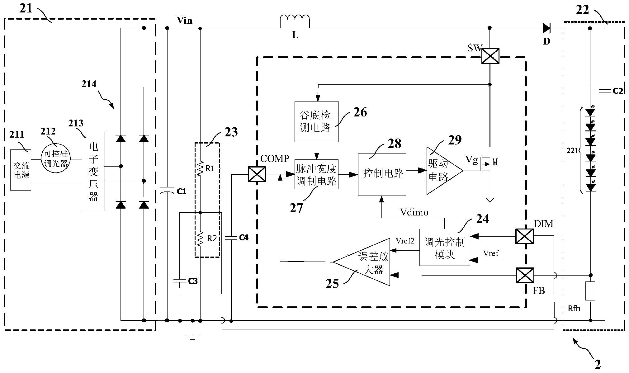
The invention provides a light-emitting diode (LED) switch constant-current driving circuit. The LED switch constant-current driving circuit comprises a voltage input module, an energy storage inductor, a freewheel diode, an LED module serving a load, a power tube for draining current and constant current, a detection module for detecting an input voltage phase state, a dimming control module connected to the detection module, an error amplifier connected to the dimming control module, a valley bottom detection circuit for detecting power tube drain voltage, a pulse width modulation circuit connected to the error amplifier and the valley bottom detection circuit, a control circuit for controlling the power tube according to detection voltage and PWM signals and a driving circuit of the power tube, wherein according to the dimming control module, input reference voltage Vref2 of the error amplifier and dimming control signals Vdimo are generated jointly through the detection voltage and reference voltage Vref1; the error amplifier enables the Vref2 to be compared with sampling voltage; and the pulse width modulation circuit is used for generating the PWM signals. According to the LED switch constant-current driving circuit, an electrolytic capacitor is not needed, an electronic transformer and a silicon controlled dimmer are compatible, the unique power tube in multiplexing simultaneously gives consideration to the draining current and the constant current, and the cost is effectively reduced.

Description

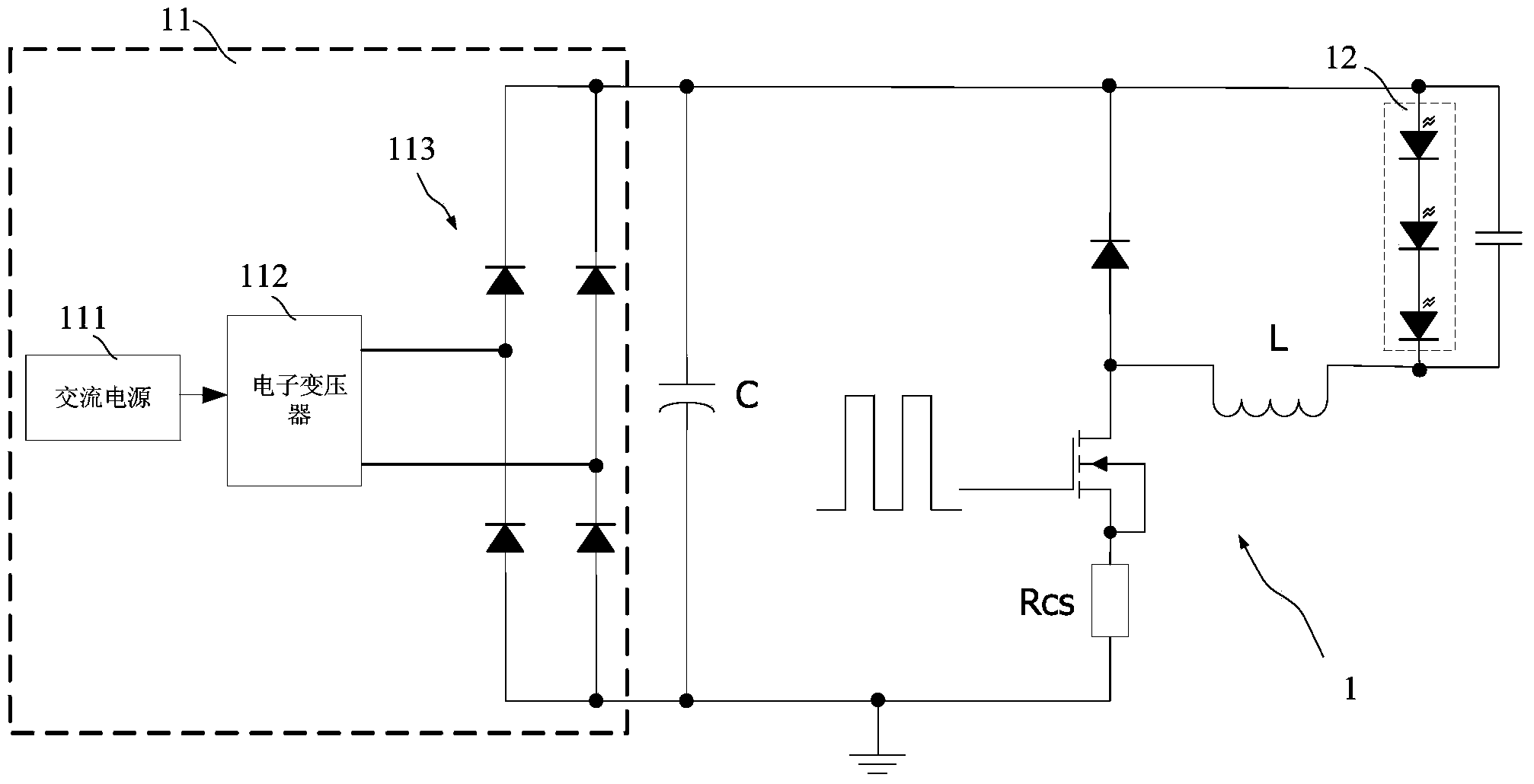
technical field [0001] The invention relates to the technical field of LED drive control, in particular to an LED switch constant current drive circuit. Background technique [0002] LED is a semiconductor device that works under low-voltage DC conditions. Under the low-voltage AC input conditions of thyristor dimmers and electronic transformers, the market demand for replacing LEDs with existing MR16 applications is very strong. On this basis The demand for compatible SCR dimmers is also considerable in the international market. However, when replacing traditional lighting fixtures such as MR16 with LEDs, some problems will be encountered: [0003] First of all, the compatibility of LEDs and electronic transformers. The current flowing through the electronic transformer must be greater than or equal to its holding current to ensure the stable and reliable operation of the electronic transformer, otherwise the electronic transformer will work intermittently or not, and the...

Claims


Application Information

Patent Timeline
IPC IPC(8): H05B37/02
Inventor 严守平蔡晓辉
Owner SHANGHAI LATRONIX TECH CORP
Why Eureka
Try Eureka