Lighting device

A lighting equipment and plane technology, applied in optical components, instruments, optics, etc., can solve the problems of expensive manufacturing and cost failure of optical devices

Active Publication Date: 2014-03-19
LIMO GMBH
View PDF3 Cites 0 Cited by
  • Summary
  • Abstract
  • Description
  • Claims
  • Application Information

AI Technical Summary

Problems solved by technology

The optics used today to generate this field are relatively expensive to manufacture and are arrayed at fixed illumination angles
More applications of uniformly tilted fields are currently held back partly by cost

Method used


Image

  • Lighting device
  • Lighting device

Examples


Embodiment Construction

[0011] In the figures, identical or functionally identical components are provided with the same reference symbols.

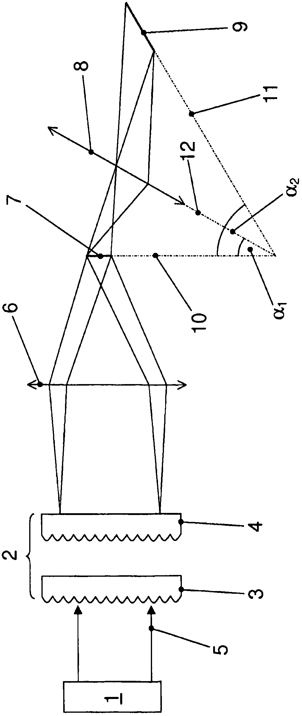
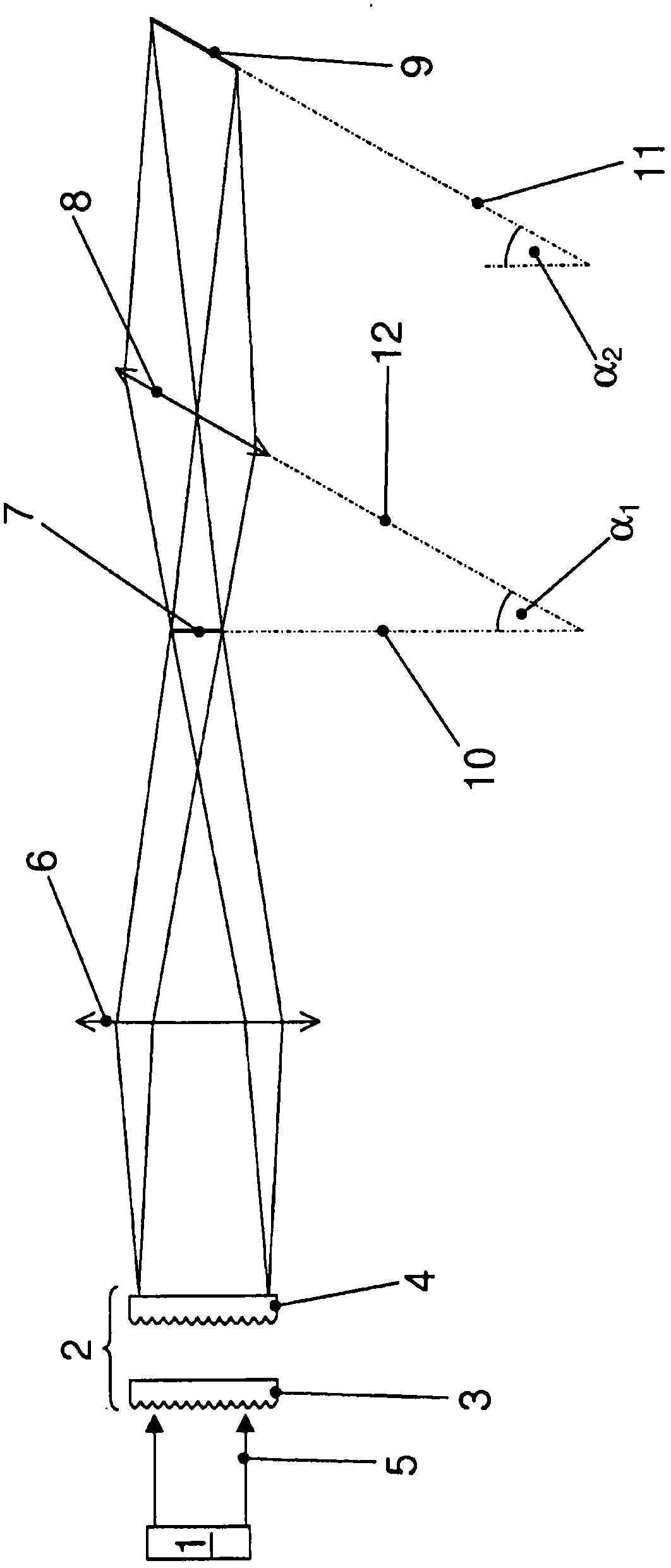
[0012] figure 1 The embodiment of the lighting device depicted in includes a light source 1 which can be formed, for example, as a semiconductor laser, in particular as a laser diode grid. At least partially not shown optical devices, such as fast-axis lenses and slow-axis lenses, etc., can be arranged behind the light source 1 in the direction of propagation.

[0013] The lighting device furthermore comprises a homogenization device 2 comprised by said optics, which in the depicted embodiment has two lens arrays 3, 4 which enable the light source 1 to The light 5 is homogenized. There is also the possibility of providing additional homogenization means, for example rectangular waveguides or diffractive optical elements (DOEs).

[0014] A Fourier lens 6 arranged downstream of the homogenization device 2 and comprised by the optical device superimposes the pa...


PUM


Abstract

Lighting device, comprising a light source (1), which can generate the light (5) used for lighting, optical means, which can generate a first field distribution (7) of the light (5) in a first plane (10), lens means (8), which are arranged downstream of the first plane (10) in the propagation direction of the light (5), such that the first field distribution (7) of the first plane (10) can be imaged by the lens means (8) into a second plane (11), such that a second field distribution (9) can arise there, wherein the plane (12) in which the lens means (8) extend and/or the second plane (11) are/is inclined relative to the first plane (10).

Description

technical field [0001] The invention relates to a lighting device according to the preamble of claim 1 . Background technique [0002] Definition: The direction of propagation of laser radiation or light refers to the intermediate direction of propagation of laser radiation or light, in particular when the laser radiation or light is not a plane wave or is at least partially divergent. Laser beams, beams, sub-beams or beams, when not expressly stated otherwise, do not refer to idealized beams of geometrical optics, but to actual beams, for example with a Gaussian profile or a modified Gaussian profile or a top hat ( Top-Hat) profile of the laser beam, which does not have an infinitesimally small, but rather broadened beam cross-section. A top-hat distribution or a top-hat intensity distribution or a top-hat profile refers to an intensity distribution which can be described substantially by a rectangular function (rect(x)) at least with respect to one direction. In this cas...

Claims


Application Information

Patent Timeline
Patent Type & Authority Applications(China)
IPC IPC(8): G02B27/09
CPCG02B27/0966G02B27/0927
Inventor T·米特拉
Owner LIMO GMBH
Why Eureka
Try Eureka