A UHF RFID planar near-field antenna with stable coverage

A near-field antenna, ultra-high frequency technology, applied in the direction of antenna, antenna grounding device, antenna grounding switch structure connection, etc., can solve the problems of blind spots, many reading blind spots, poor edge control, etc., and achieves steep edge attenuation and elimination. The effect of reading blind spots, uniform field distribution

Active Publication Date: 2021-11-02
SHENZHEN UNIV
View PDF9 Cites 0 Cited by
  • Summary
  • Abstract
  • Description
  • Claims
  • Application Information

AI Technical Summary

Problems solved by technology

However, if the antenna design is unreasonable, the edge induction field is not suppressed enough, and non-target tags outside the antenna aperture are also read, which will cause cross-reading.
In addition, if the field strength distribution is uneven within the specified aperture range of the antenna, blind spots will appear, resulting in missed reading of tags
Most of the near-field antennas on the market have the problem of poor edge control or many reading blind spots. It is rare to see a low-cost near-field antenna that can solve these two problems at the same time.
In addition, most of the microstrip near-field antennas on the market are based on a multi-layer PCB structure, and the antenna radiation structure and feed network are distributed on different layers. Although this reduces the difficulty of design, it greatly increases the cost of the antenna.

Method used


Image

  • A UHF RFID planar near-field antenna with stable coverage
  • A UHF RFID planar near-field antenna with stable coverage
  • A UHF RFID planar near-field antenna with stable coverage

Examples


Embodiment 1

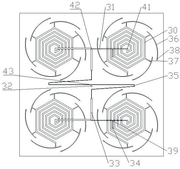
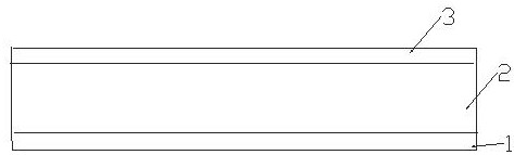
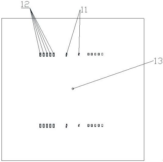
[0033] see figure 1 , figure 2 as well as image 3 , a UHF RFID planar near-field antenna with stable coverage, comprising a metal floor 1, a dielectric plate 2 and a radiation layer 3 stacked in sequence; the radiation layer 3 is composed of a power dividing network and N radiators; the power The sub-network is located in the middle of the radiation layer 3, and the radiator is evenly distributed around the power sub-network; the radiator includes a radiator, a first jumper 11, a second jumper group, and an absorption branch assembly; The radiator is located in the middle of the radiator, and the absorption stub assembly surrounds the radiator; the power division network includes a first microstrip group, and the first microstrip 31 in the first microstrip group The number matches the number of the radiator; the radiator is composed of a main microstrip 30; one end of the first microstrip 31 is connected to one end of the main microstrip 30, and the connecting point is a f...

Embodiment 2

[0038] On the basis of the above structure, N is 4, that is, four radiators are provided; the four first microstrips 31 are all parallel to each other; the ends of the two first microstrips 31 away from the first point 41 are connected At a second point 42, the ends of the other two first microstrips 31 away from the first point 41 are connected to another second point 42; the power dividing network also includes the second microstrip 32 and two V shaped microstrip 35; one end of the second microstrip 32 is connected to the feed input terminal 13, and the other end is connected to two V-shaped microstrips 35; the second microstrip 32 is connected to the V The connection point of the shaped microstrip 35 is the third point 43; the third point 43 is located at the center of the power distribution network, and the two second points 42 are separated from the two sides of the third point 43; the two V-shaped The microstrip 35 is symmetrical about the center of the third point 43; s...

Embodiment 3

[0041] On the basis of the above structure, along the direction toward the first lumped element 38 , the distance from the arc-shaped microstrip 36 to the first point 41 gradually increases, improving the ability to absorb the steep edge attenuation of the stub components.


PUM


Abstract

The invention provides a UHF RFID planar near-field antenna with stable coverage, which includes metal floors, dielectric plates and radiation layers stacked in sequence; the radiation layer is composed of a power distribution network and 2 to 4 radiators; the power distribution network is located at the radiation In the middle part of the layer, the radiator is evenly distributed around the power distribution network; the radiator includes the radiator, the first jumper, the second jumper group and 3~18 groups of absorbing branches; the radiator is located in the middle of the radiator, and the absorbing branches Surrounding the radiator; the power division network includes the first microstrip whose number matches the number of radiators; the radiator is composed of the main microstrip; one end of the first microstrip is connected to one end of the main microstrip at the first point; the main body The microstrip rotates and extends around the first point; the absorbing branch includes an arc-shaped microstrip and the first lumped element; one end of the arc-shaped microstrip is grounded through the first lumped element, and the other end is located outside the radiation body with the main microstrip The position of the edge is connected; the current direction of the arc microstrip is opposite to the current direction of the main microstrip.

Description

technical field [0001] The invention relates to the technical field of antennas, in particular to an ultra-high frequency RFID planar near-field antenna with stable coverage. Background technique [0002] Radio Frequency Identification (RFID) technology has developed rapidly and has been widely used in various fields, especially warehouse management, intelligent logistics, unmanned retail, smart home, smart wearable devices and other industries. In the practical application of various industries, the working environment of RFID systems is becoming more and more complex, and the read-write antennas and electronic tags are also becoming more miniaturized, lightweight and ultra-thin. In such an environment, to improve the reading speed and reading accuracy of the system, higher requirements are put forward for the RFID system. Among them, the read-write antenna is an important component that affects the performance of the RFID system. The far and near field distribution of the...

Claims


Application Information

Patent Timeline
Patent Type & Authority Patents(China)
IPC IPC(8): H01Q1/38H01Q1/50H01Q1/48H01Q17/00
CPCH01Q1/38H01Q1/50H01Q1/48H01Q17/008
Inventor 张晓张聪
Owner SHENZHEN UNIV
Why Eureka
Try Eureka