Tubular bag machine for filling a product

A technology for filling pipes and hoses

Active Publication Date: 2014-08-20
星德科包装解决方案私人有限责任公司
View PDF7 Cites 0 Cited by
  • Summary
  • Abstract
  • Description
  • Claims
  • Application Information

AI Technical Summary

Problems solved by technology

A particular disadvantage here is that, depending on the tube diameter used, the emitted electromagnetic wavelength and the coupling on the machine side of the sensor, different electromagnetic field geometries result

Method used


Image

  • Tubular bag machine for filling a product
  • Tubular bag machine for filling a product
  • Tubular bag machine for filling a product

Examples


Embodiment Construction

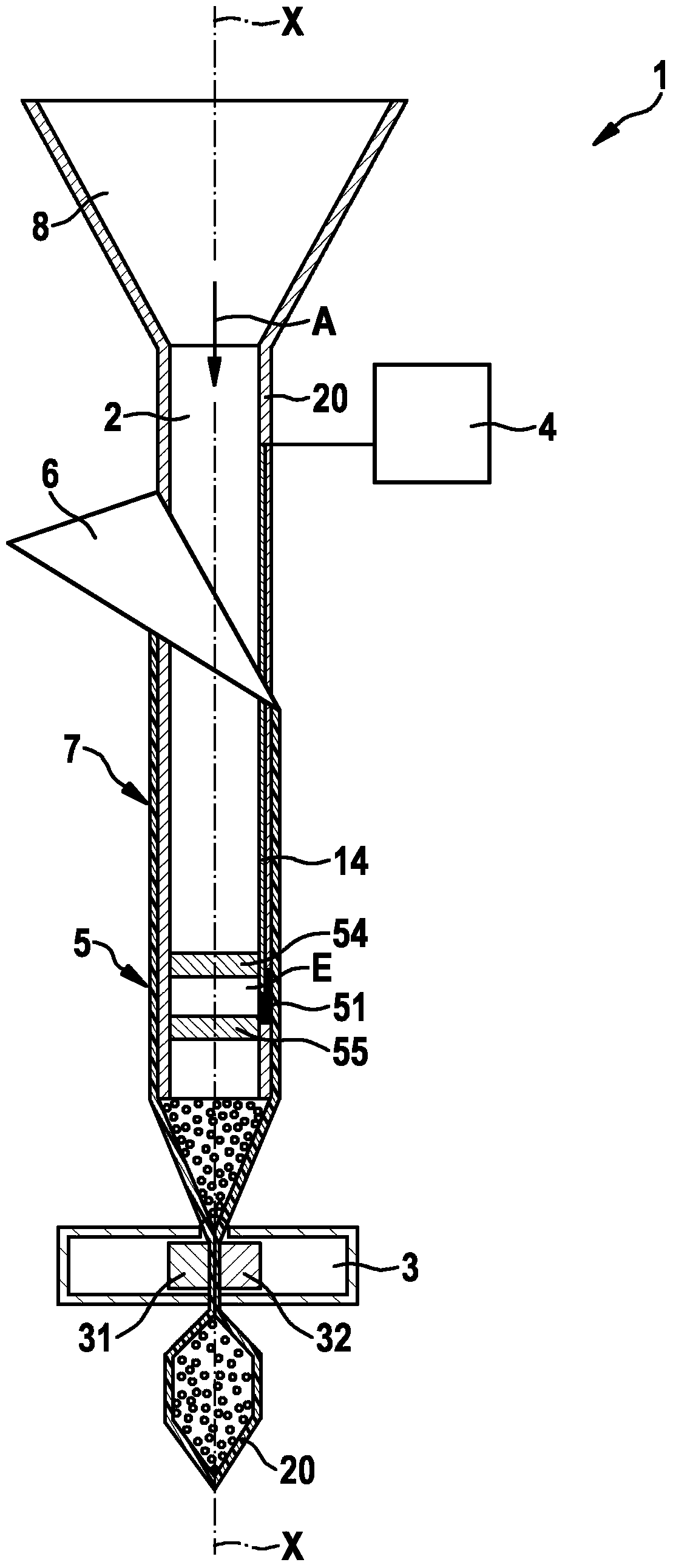
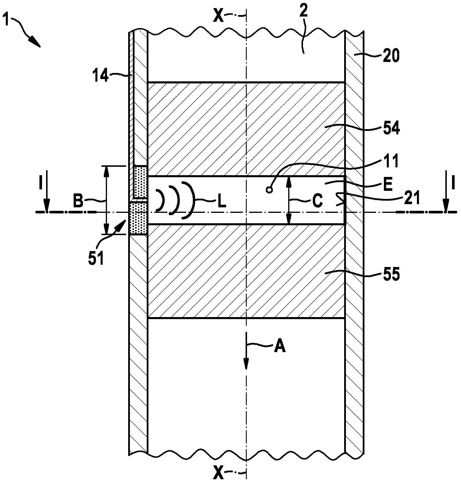
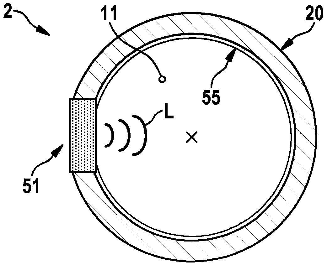
[0019] Refer below figure 1 -3 Describe in detail the hose bag machine for filling products according to a preferred embodiment.

[0020] figure 1 A schematic sectional view of a hose bag machine 1 for filling products according to a preferred embodiment of the invention is shown. The tube bag machine 1 comprises a filling funnel 8 in which the product to be filled is supplied in portions in a falling direction A to a vertical filling pipe 2 fastened thereto. Via the forming shoulder 6, the circulatingly fed packaging material is formed around the filling tube 2 into an elongated packaging material tube 7, which is longitudinally sealed by means of a longitudinal sealing seam, not shown here, by means of a longitudinal sealing unit. welding. The tube bag machine 1 also includes a transverse sealing unit 3 with first and second horizontal sealing jaws 31 , 32 , which is arranged at the end of the filling tube 2 opposite the filling funnel 8 . The horizontal sealing unit 3 f...


PUM


Abstract

The invention relates to a tubular bag machine for filling a product into bags, comprising a vertical filling tube (2), a transverse sealing unit (3), a control unit (4) for controlling the tubular bag machine, and a sensor device (5) for detecting the product in the filling tube (2), which is designed to detect the product falling through the filling tube (2), wherein the sensor device (5) has a sensor (51) for emitting electromagnetic waves, and which is connected to the control unit (4), wherein the electromagnetic waves emitted by the sensor (51) remain in a detection space (E) which is confined to one region at the filling tube (2).

Description

technical field [0001] The invention relates to a hose bag machine for filling products. Background technique [0002] The prior art discloses vertical hose bag machines of different configurations. In this case, the product elements of the product to be filled are detected by means of a sensor device in order to determine the product quantity filled into the tube bag. In this case, sensors are used which emit, for example, roentgen rays or electromagnetic waves in the microwave range and which are arranged along the drop section on the outside of the filling tube. Such a hose bag machine is known, for example, from DE 10 2006 013 663 A1. A particular disadvantage here is that, depending on the tube diameter used, the emitted electromagnetic wavelength and the machine-side coupling of the sensor, different electromagnetic field geometries result. As a result, the sensor not only detects a large section of the falling section, but possibly even objects outside the filling ...

Claims


Application Information

Patent Timeline
Patent Type & Authority Applications(China)
IPC IPC(8): B65B1/30B65B9/20B65B57/14
CPCB65B9/20B65B9/10B65B57/145B65B1/30B65B57/10
Inventor J·塞德尔W·泽格尔S·舒尔特斯D·艾歇尔
Owner 星德科包装解决方案私人有限责任公司
Why Eureka
Try Eureka