steerable tip endotracheal tube

A technology for tracheal tubes and ventilation tubes, applied in the field of medical devices, can solve problems such as lack of control parts, uncertain ability of the tube to restore its original shape, and influence of tube curvature, so as to improve the success rate of intubation, avoid over-reliance, and cost cheap effect

Active Publication Date: 2015-10-21
芜湖启博知识产权运营有限公司
View PDF7 Cites 0 Cited by
  • Summary
  • Abstract
  • Description
  • Claims
  • Application Information

AI Technical Summary

Problems solved by technology

But there are certain deficiencies: 1. The bending position of the tip of the catheter is not determined enough, and the bending degree of the overall catheter will be affected during operation, and the operation activities in a limited space are limited.
2. The tip of the catheter is slightly soft, and the ability of the catheter to return to its original shape after the operation of bending the top is not sure enough
3. The catheter is slightly soft and has no effective support. It is easily deformed by the influence of surrounding tissues and affects the effective ventilation space, such as changes in the body position during the operation (such as simple head elevation), and the catheter passes through physiological bending (such as the bifurcation of the trachea) , violent intubation, etc.
The catheter is deformed, the ventilation space becomes smaller, and the airway resistance increases. Especially in the case of increased airway secretions, the suction tube cannot pass normally, which may cause fatal risks
4. The technique of blind nasal intubation is contradictory with the operation of the pull ring, and it is difficult to realize it at the same time
5. The tip of the catheter is only slightly soft, and the control wire runs a long time inside the tube wall. Pulling the bracelet, it takes a lot of force to make the tip upturned. Excessive force will inevitably explode
6. The bending degree of the tip of the fixed catheter remains unchanged, and the finger has to keep pulling the ring to do it, and there is a lack of control parts

Method used


Image

  • steerable tip endotracheal tube
  • steerable tip endotracheal tube
  • steerable tip endotracheal tube

Examples


Embodiment Construction

[0024] The present invention will be further described below in conjunction with specific embodiments.

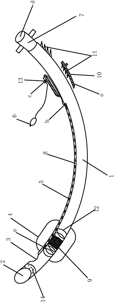
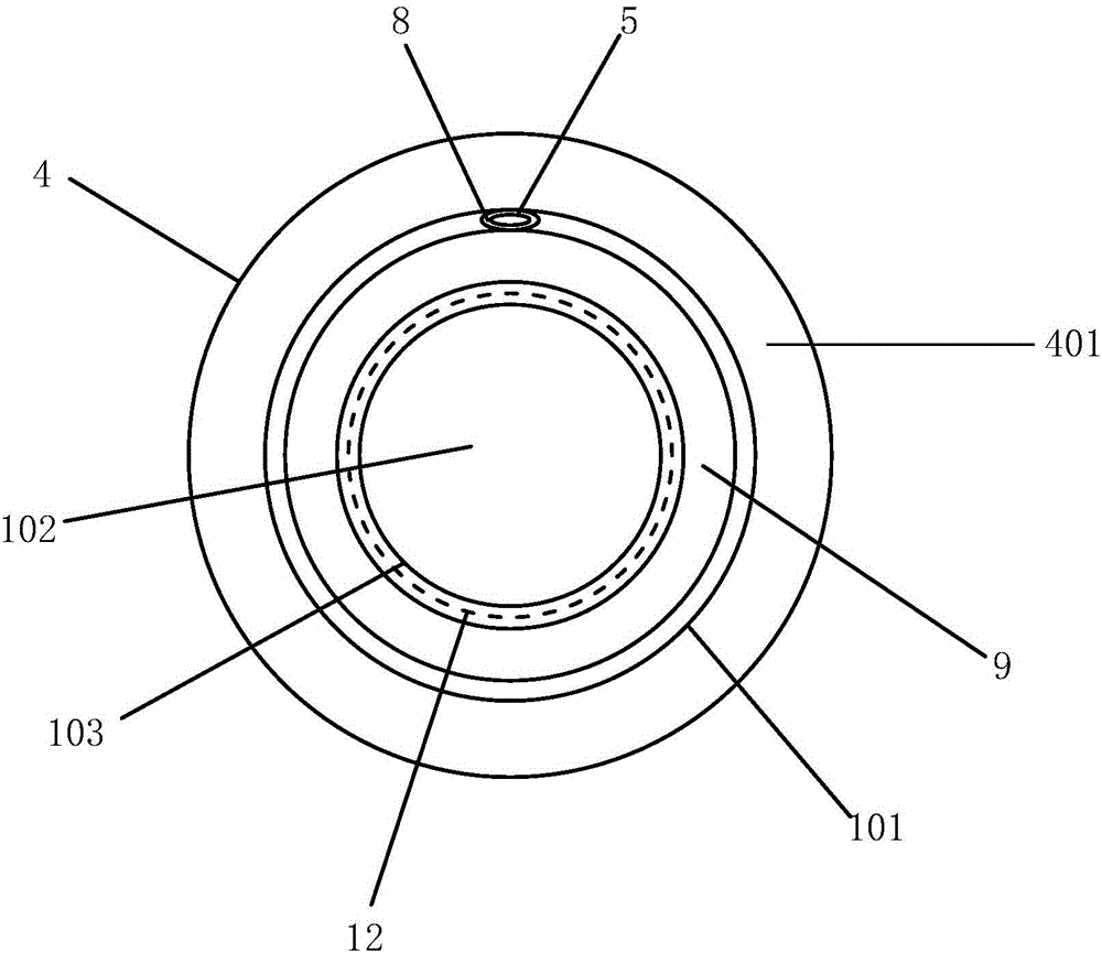
[0025] like figure 1 A tip controllable endotracheal tube is shown, which includes a tube 1, the front end of the tube 1 is provided with a beveled opening 2, a side port 3 is provided on the side near the front end of the tube 1, and a side port 3 is provided on the outer periphery of the tube 1 close to the side port 3 airbag4. The air bag 4 is usually not inflated, and the air bag 4 is inflated after passing through the glottis. A ventilation duct 5 is arranged on the front side wall of the duct 1 . The front end opening of the ventilation conduit 5 communicates with the inner side of the front end inner wall of the air bag 4 , and the end of the ventilation conduit 5 is provided with an inflation port 6 . figure 1 The pipe wall of the ventilation conduit 5 shown at a is integrated with the inner wall of the airbag 4 , and the ventilation conduit 5 protrudes from the ...


PUM


Abstract

The invention relates to a tracheal catheter with a controllable top end. The tracheal catheter comprises a catheter body, wherein the front side wall of the catheter body is provided with a ventilation catheter body, the front opening of the ventilation catheter body is communicated with the inner wall of the front end of an air bag, the front side wall of the catheter body is provided with a cavity, the ventilation catheter body penetrates through the cavity, a flexible part is arranged on the position, in the middle of air bag, of the catheter body, and the front end of the ventilation catheter body is fixed on the catheter body wall in the direction of the top end of the flexible part of the catheter body. A handle is arranged on the position, close to the joint end of a breathing loop, of the catheter body, the handle is provided with a ventilation catheter body fixing device, and the rear inner side of the handle and the outer side of one side corresponding to the catheter body are provided with clamping teeth matched with each other. The flexible part is arranged in the position, on the air bag, of the catheter body, and connected with the ventilation catheter body, the ventilation catheter body is drawn to achieve controllability of the bending degree of the top end of the catheter body, the ventilation catheter body fixing device on the handle is used for fixing the bending position, and the intubation success rate can be increased. A paramagnetic device arranged between the opening on the inclined surface and the opening on one side of the catheter body facilitates automatic glottis identification of the top end of the catheter body, and excessive dependence on a laryngoscope is avoided.

Description

technical field [0001] The invention relates to the field of medical devices, in particular to a tracheal catheter for clinical control of the respiratory tract. Background technique [0002] Clinically, general anesthesia is used to control breathing, respiratory insufficiency, and respiratory failure for emergency resuscitation and airway opening. Tracheal intubation technology is required. This technology is necessary for departments such as anesthesiology, ICU, emergency department, and neonatology. Anesthesia techniques must be mastered by relevant medical personnel. [0003] Endotracheal intubation is divided into orotracheal intubation, nasal endotracheal intubation, and tracheostomy intubation according to the route of endotracheal tube insertion. According to whether the laryngoscope is used to visualize the throat anatomy, it can be divided into bright vision intubation method and blind detection intubation method. With the advancement of science and technology, ...

Claims


Application Information

Patent Timeline
Patent Type & Authority Patents(China)
IPC IPC(8): A61M16/04
Inventor 王丽娥鲍永新闫作丽王琦鲍永岩王锡彬
Owner 芜湖启博知识产权运营有限公司
Why Eureka
Try Eureka