
Oil treating apparatus

A treatment device and oil technology, applied in the direction of filtration and separation, separation methods, chemical instruments and methods, etc., can solve the problems of poor filtration effect, poor atomization effect, water content in oil liquid, high gas content rate, etc., and achieve improved vaporization effect , Strong degassing ability and better filtering effect

Inactive Publication Date: 2014-03-26
重庆市合川区何茗机械加工厂
View PDF0 Cites 0 Cited by
  • Summary
  • Abstract
  • Description
  • Claims
  • Application Information

AI Technical Summary

Problems solved by technology

The oil treatment device with this structure has poor filtering effect and poor atomization effect, and the atomized oil contains high water and gas content.

Method used


Image

  • Oil treating apparatus
  • Oil treating apparatus
  • Oil treating apparatus

Examples


Embodiment Construction

[0016] The present invention will be described in further detail below in conjunction with the accompanying drawings and specific embodiments.

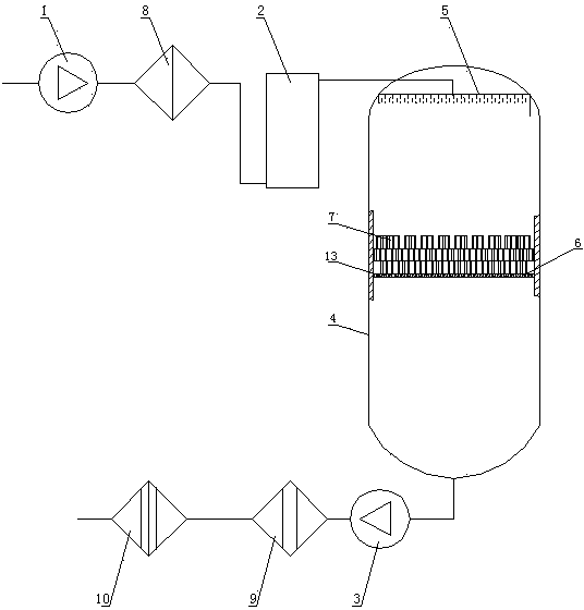
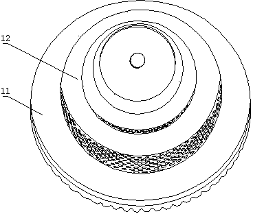
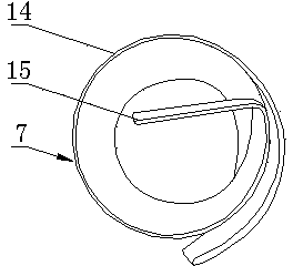
[0017] Such as figure 1 As shown, the oil treatment device includes an oil inlet pump 1, an oil heater 2, a vacuum separation device, an oil outlet pump 3 and a filter. The vacuum separation device includes a vacuum tank 4 , an atomizer 5 and a reaction frame arranged in the vacuum tank, and the filter includes a primary filter 8 , a secondary filter 9 and a fine filter 10 . The inner wall of the filter element 11 of the primary filter 8, the secondary filter 9 and the fine filter 10 is provided with a disturbance ring 12 of a spiral structure, such as figure 2 As shown, the oil liquid entering the filter forms a spiral flow, the filter core of the primary filter 8 adopts a single-layer filter screen, and the filter core of the secondary filter 9 adopts a three-layer filter screen. The filter core of fine filter 10 adopts three-lay...


PUM

PropertyMeasurementUnit
thicknessaaaaaaaaaa

Abstract

The invention discloses an oil treating apparatus, comprising an oil feeding pump, an oil heater, a vacuum separator, an oil discharging pump and a filter. The vacuum separator comprises a vacuum tank, an atomizer and a reaction rack, wherein the atomizer and the reaction rack are arranged in the vacuum tank. The filter comprises a primary filter, a secondary filter and a fine filter, and the oil feeding pump, the primary filter, the oil heater, the vacuum separator, the oil discharging pump, the secondary filter and the fine filter are successively connected. The reaction comprises a support plate horizontally arranged on a cross section in the vacuum tank and three layers of reaction rings arranged on the support plate. Oil passes through the primary filter and then undergoes vacuum vaporization, then oil is filtered by the secondary filter and the fine filter, so a better filtering effect is obtained; high temperature oil enters into the atomizer in the vacuum separator, forms a mist at first through the atomizer and then forms a film, oil mist adheres onto the reaction rings and the support plate during falling, so the oil treating apparatus has a contact area in vacuum increased by nearly one hundred times compared with an original contact area and has strong dewatering capability and degassing capability.

Description

technical field [0001] The invention relates to an oil filter, in particular to an oil treatment device used on the oil filter. Background technique [0002] Due to the existing firepower, hydraulic power, nuclear power, gas, waste heat power generation, chemical industry, papermaking, metallurgy and other equipment systems, leakage, poor sealing, long-term thermal load of oil, open oil storage, etc., in the air The moisture and gas infiltrate into the oil, resulting in water and gas in the oil. [0003] Therefore, an oil filter is often used to achieve online filtration and purification, so that the oil in operation can be purified in time before it deteriorates, and the moisture, gas and impurities in the oil can be removed quickly and efficiently. Make the indicators of the oil products in operation meet the national standards, and ensure the normal operation of the unit's adjustment system and lubrication system. [0004] The oil treatment device is an important part o...

Claims


Application Information

Patent Timeline
Patent Type & Authority Applications(China)
IPC IPC(8): B01D36/02
Inventor 邓方兰
Owner 重庆市合川区何茗机械加工厂
Learn More