Hydraulic side pressing die

A blank holder and mold technology, applied in forming tools, manufacturing tools, metal processing equipment, etc., can solve the problems of high replacement cost, high scrap rate, high blank holder force, avoid flat wrinkle deformation, stable product quality, The effect of improving production efficiency

Inactive Publication Date: 2014-03-26
SHANDONG SPECIAL INDUSTRY GROUP CO LTD
View PDF15 Cites 3 Cited by
  • Summary
  • Abstract
  • Description
  • Claims
  • Application Information

AI Technical Summary

Problems solved by technology

As a result, the initial mold stroke is small and the blank-holding force is low, so it cannot meet the initial deformation requirements during the product folding forming process. High blank-holding force
Make the product swim during the bending forming process, damage the positioning pin of the mold, the size is out of tolerance, the workpiece appears wrinkled and deformed, the mold is easy to jam the workpiece, and the scrap rate is high
At the same time, as the mold continues to rise and close the mold, the compression of the polyurethane rubber block increases and the blank holder force increases, which increases the lifting force of the hydraulic equipment, power consumption, and frequent replacement of the polyurethane rubber block. The cost is high and the labor intensity is high.

Method used


Image

  • Hydraulic side pressing die
  • Hydraulic side pressing die

Examples


Embodiment Construction

[0013] Embodiments of the present invention are further described below in conjunction with accompanying drawings:

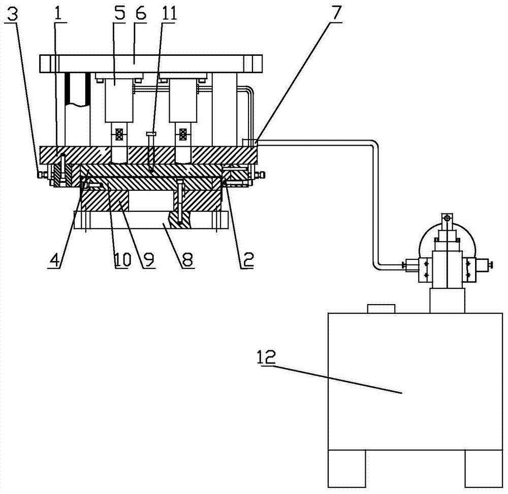
[0014] Such as figure 1 The shown hydraulic edge blanking mold includes a mold base 1, a concave formwork assembly 2 is installed under the mold base 1, and adjusting screws 3 are arranged on both sides of the concave formwork assembly 2. The concave formwork assembly 2 is generally formed by splicing a plurality of mold pieces to form a die , Adjust the gap between the female template assembly 2 and the punch by adjusting the screw 3. A blank holder stripper 4 is installed in the concave template assembly 2, and the blank blank blank 4 moves up and down in the concave template assembly, and can pass through slide rails or other sliding structures. The blank-holding stripper plate 4 is connected with the hydraulic cylinder 5, and the hydraulic cylinders 5 are fixed on the upper plate 6 of the formwork. The hydraulic cylinders 5 are respectively connected with t...


PUM


Abstract

The invention relates to a hydraulic side pressing die which is characterized by comprising a die-set. A female die plate component is installed below the die-set. The two sides of the female die plate component are provided with adjusting screws. A side pressing material returning plate is installed inside the female die plate component and moves up and down inside the female die plate component. The side pressing material returning plate is connected with hydraulic cylinders. The multiple hydraulic cylinders are fixed to an upper plate of the die-set and connected with distributors through oil tubes respectively. The distributors are connected with a hydraulic system through oil pipes at the same time. A subplate is installed at the upper portion of a lower die base of the die-set. A male die fixing plate is installed at the upper portion of the subplate. A male die is fixed to the male die fixing plate. A positioning pin is arranged on the surface of the male die fixing plate. Due to enough pressing force, moving displacement of a workpiece in the bending process is avoided, plane wrinkles and deformation are avoided, the product quality is stable, the production efficiency is improved by more than 4 times, and the hydraulic side pressing die has the advantages of being simple in structure, high in automation degree, constant in side pressing force and the like.

Description

technical field [0001] The invention relates to a hydraulic pressure edge die. Background technique [0002] At present: In the bending and forming operation of irregular large-scale thin plate parts, the mold is placed in the lifting hydraulic equipment, and the movable slider of the lifting hydraulic equipment is used to move up and move, and the convex and concave molds of the forming mold are closed to realize irregular large thin plate parts. Bending and forming operations. [0003] The blank-holding force of the conventional molding die is achieved by the elastic compression of multiple rubber plates. The movable slider of the upward-lifting hydraulic equipment moves up and acts on the rubber fixed plate to gradually compress the polyurethane rubber block to realize the folding of irregular large-scale thin plate parts. Bending force for forming. [0004] Due to the initial deformation of the product during the hemming forming process, the blank-holding force is requ...

Claims


Application Information

Patent Timeline
Patent Type & Authority Applications(China)
IPC IPC(8): B21D19/00B21D37/10
Inventor 徐其君王勇陈凌云赵则元
Owner SHANDONG SPECIAL INDUSTRY GROUP CO LTD
Why Eureka
Try Eureka