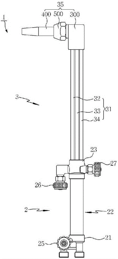
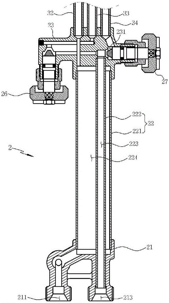
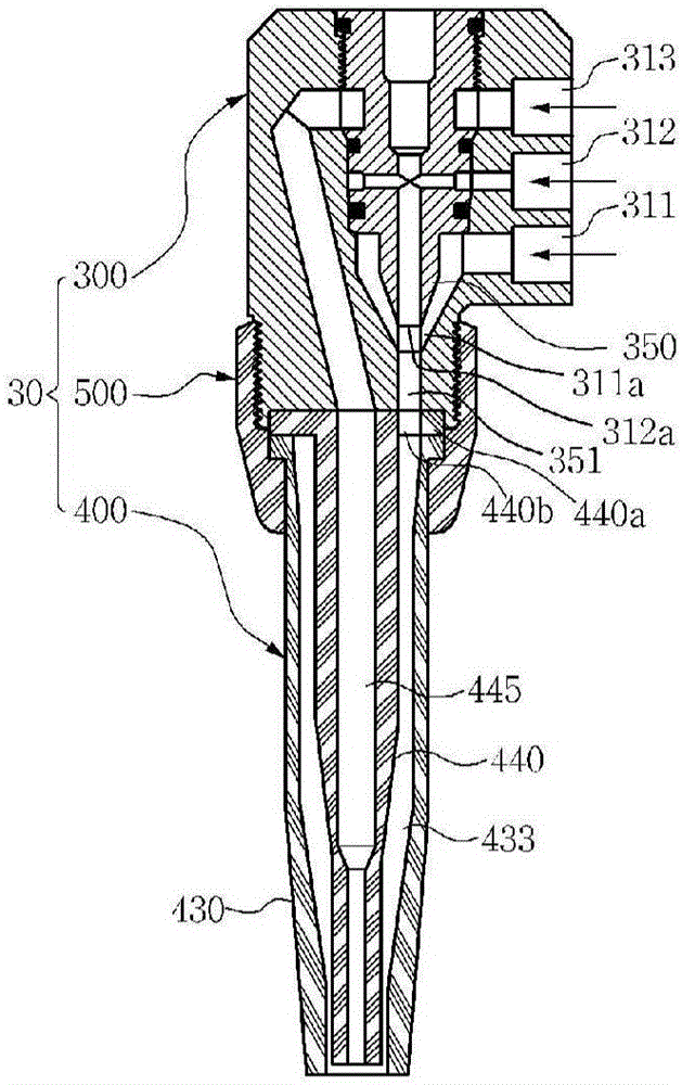
Gas cutter

A gas cutting machine, oxygen technology, applied in gas flame welding equipment, welding equipment, metal processing equipment, etc., can solve the problems of reduced preheating performance, maintaining uniform flame and pressure, cumbersome assembly operations, etc., to minimize pressure changes. Effect

Inactive Publication Date: 2016-06-15
(株)火火 +1
View PDF7 Cites 0 Cited by
  • Summary
  • Abstract
  • Description
  • Claims
  • Application Information

AI Technical Summary

Problems solved by technology

[0038] However, in the conventional tip 400, at the front end of the outer tip 430, a plurality of mixed gas injection ports 435 are arranged around the cutting oxygen injection port 446, and if small foreign matter flows into the mixed gas injection port 435 and clogs, Then there is a problem that it is very difficult to remove the foreign matter. Since the flame is formed by the mixed gas ejected through the plurality of mixed gas injection ports 435, it is impossible to follow the part where the mixed gas injection port 435 is formed and the part that is not formed. The circumferential direction centered on the cutting oxygen injection port 446 maintains a uniform flame and pressure, which

Method used


Image

  • Gas cutter
  • Gas cutter
  • Gas cutter

Examples


Embodiment Construction

[0123] While the present invention is capable of various modifications and embodiments, specific embodiments are illustrated in the drawings and described in detail. However, this is not intended to limit the present invention to specific embodiments, and it should be understood that all changes, equivalents, and substitutions included in the spirit and technical scope of the present invention are included. In describing the present invention, when it is judged that the detailed description of the relevant known technology may obscure the gist of the present invention, its detailed description will be omitted.

[0124] Embodiments of the present invention will be described in detail below with reference to the accompanying drawings.

[0125] First, in describing an embodiment of the present invention, the same reference numerals will be assigned to the same parts as those of the gas cutting machine described above, and will be described.

[0126] exist Figure 7 to Figure 14...


PUM


Abstract

The purpose of the present invention is to provide a head for a gas cutter which, due to minimizing a pressure change occurrence caused by a pressure difference in a mixed gas passageway, is capable of maintaining preheating performance by smoothly spraying mixed gas and stably forming a flame, and which is capable of maximally inhibiting backfire occurrence caused by a mixed gas pressure difference within the head. In addition, the purpose of the present invention is to provide a head for a gas cutter which allows even an unskilled person to very promptly and conveniently combine a head frame and a tip, which constitute the head, in such a manner that an injecting flow path provided to the head frame and the mixed gas passageway provided to the tip are in communication with each other, simultaneously allowing the laminar flow movement of preheated oxygen and fuel gas by efficiently configuring the injecting flow path of an injecting part, which is capable of preventing backfire by minimizing the pressure difference within the mixed gas passageway after the preheated oxygen and the fuel gas are mixed, and which is capable of extending the life span by minimizing the heating of the head as well as being capable of increasing heat efficiency by improving the mixing ratio of the mixed gas, without allowing the flame to reach the head even if a backfire occurs.

Description

technical field [0001] The present invention relates to a gas cutting machine, and more specifically, relates to a method that minimizes the pressure change of the mixed gas that is mixed with preheated oxygen and fuel gas for heating the material to be processed and sprayed out, so that the mixed gas can be sprayed out smoothly. At the same time, it is a gas cutting machine that can suppress the backfire phenomenon to the greatest extent. Background technique [0002] Generally speaking, the head for a gas cutting machine is configured so that while cutting oxygen is sprayed toward the center of the tip of the head, a preheating flame for preheating the material to be processed is formed around the cutting oxygen. It is formed by igniting a mixed gas generated by mixing gaseous oxygen and fuel gas supplied to the tip. [0003] In order to form a preheating flame, a general gas cutting machine uses a torch mixing method and a burner mixing method according to the method of ...

Claims


Application Information

Patent Timeline
IPC IPC(8): B23K7/10
Inventor 康义昌李明姬
Owner (株)火火
Why Eureka
Try Eureka