Manufacturing method for pulling boring machine boring rod central frame

A production method and center frame technology, which are applied in the direction of manufacturing tools, boring/drilling, large fixed members, etc., can solve problems such as damage to the boring bar, increase the deviation of the machined hole, affect the service life of the boring bar, etc. Convenient and reliable, prolong service life, simple and reasonable structure

Inactive Publication Date: 2014-03-26
QINGDAO NPA IND
View PDF0 Cites 1 Cited by
  • Summary
  • Abstract
  • Description
  • Claims
  • Application Information

AI Technical Summary

Problems solved by technology

[0004] The support sleeve of the boring machine cannot be adjusted. During the boring work, the boring bar is easy to collide with the support sleeve, causing more scratches on the surface of the boring bar, resulting in serious damage to the boring bar and affecting the service life of the boring bar; Due to the collision and friction of the support sleeve, the gap between the two continues to increase, resulting in an increase in the vibration of the boring bar, resulting in a center shift, which in turn increases the deviation of the processed hole, affects the processing quality, and the scrap rate remains high; The non-adjustable support sleeve in the prior art, the collision friction between it and the boring bar not only affects the service life of the boring bar and the quality of the processed hole, but also affects the service life of the support sleeve itself, frequent replacement of the boring bar and the support sleeve, resulting in machining Waste of equipment resources and increase in processing costs

Method used


Image

  • Manufacturing method for pulling boring machine boring rod central frame

Examples


Embodiment

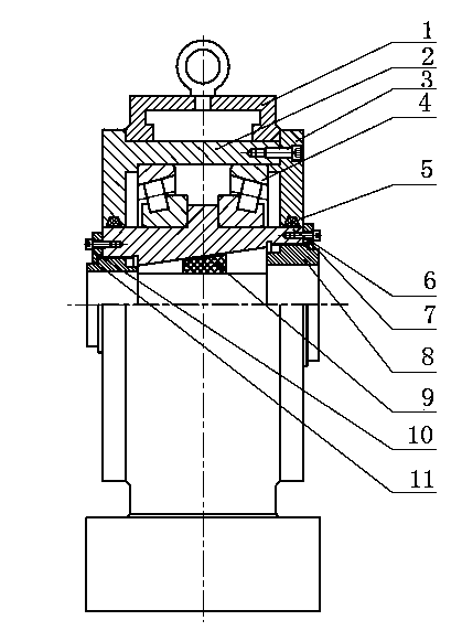
[0018] Reference figure 1 , The manufacturing method of the boring bar center frame of the pull boring machine of this embodiment is to install the support seat 1, the bearing outer cover 2, the bearing adjusting and fixing plate 3, the roller bearing 4, the blanket gasket 5, the bearing inner sleeve 6, and the right adjusting thread according to the drawings. Fixing plate 7, right adjusting thread 8, adjustable taper sleeve 9, left adjusting screw fixing plate 10 and left adjusting thread 11, the boring bar passes through the central bore of the bearing inner sleeve 6, the central bore of the bearing inner sleeve 6, the middle section is The cone-shaped, adjustable cone sleeve 9 is installed between the boring bar and the bearing inner sleeve 6. The adjustable taper sleeve 9 is in the shape of a frustum, the central aperture of the adjustable taper sleeve 9 is mounted on the bearing inner sleeve 6 as a frustum-shaped section, and the smallest diameter of the adjustable taper s...


PUM


Abstract

The invention discloses a manufacturing method for a pulling boring machine boring rod central frame. The manufacturing method comprises the step that a supporting base, a bearing outer sleeve, a bearing adjusting fixing board, a roller bearing, a blanket cushion sealing ring, a bearing inner sleeve, a right adjusting thread fixing board, right adjusting threads, an adjustable taper sleeve, a left adjusting thread fixing board and left adjusting threads are installed according to drawings. The clearance between the frustum-shaped adjustable taper sleeve and a boring rod is proper, wherein the adjustable taper sleeve of the pulling boring machine boring rod central frame is made of nylon materials, vibration is effectively avoided, the quality of a machined hole is ensured, collision is effectively avoided at the same time, and the service life of the boring rod is prolonged; due to the fact that the right adjusting thread fixing board, the right adjusting threads, the left adjusting thread fixing board and the left adjusting threads are arranged, the adjustable taper sleeves of different inner diameters can be replaced conveniently to enable the taper sleeves to be matched with boring rods of different diameters for use, the best using state is achieved, the structure is simple and reasonable, and use is convenient and reliable.

Description

[0001] Technical field [0002] The invention belongs to a manufacturing method of a boring bar support device of a boring deep hole machine tool, and in particular relates to a manufacturing method of a boring bar center frame of a stretch boring machine. [0003] Background technique [0004] The support sleeve of the pulling boring machine cannot be adjusted. During the boring work, the boring bar easily collides with the support sleeve, causing more scratches on the surface of the boring bar, causing serious damage to the boring bar and affecting the service life of the boring bar; Due to the collision and friction of the support sleeve, the gap between the two continues to increase, which causes the vibration of the boring bar to increase, which leads to the center shift, which in turn increases the deviation of the processed hole, affects the processing quality, and the reject rate remains high; In the prior art non-adjustable support sleeve, its collision and friction with t...

Claims


Application Information

Patent Timeline
Patent Type & Authority Applications(China)
IPC IPC(8): B23B29/14B23B41/02
CPCB23Q1/76
Inventor 古朝雄
Owner QINGDAO NPA IND
Why Eureka
Try Eureka