Angle-adjustable polisher

A polishing machine and adjustable technology, applied in the field of polishing machines, can solve the problems of inability to realize large-scale application, high manufacturing cost, inconvenient operation, etc.

Active Publication Date: 2014-03-26
平湖佐越机械制造股份有限公司
View PDF7 Cites 8 Cited by
  • Summary
  • Abstract
  • Description
  • Claims
  • Application Information

AI Technical Summary

Problems solved by technology

The polishing effect of this invention is very good, but its manufacturing cost

Method used


Image

  • Angle-adjustable polisher
  • Angle-adjustable polisher

Examples


Embodiment Construction

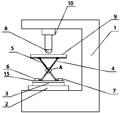
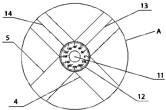
[0015] like figure 1 and figure 2 A polishing machine with an adjustable angle is shown, and its structure includes a fuselage 1, a polishing device connected to the top of the fuselage 1, and a workbench 9; the fuselage 1 is also provided with an omnidirectional transmission device, which An angle adjustment device is arranged on the top, and the angle adjustment device is movably connected with the workbench 9. The polishing device is composed of a rotating motor 10 and a grinding head 8 fixedly connected, and the rotating motor 10 is connected to the top of the fuselage 1 . During operation, the workpiece to be processed is fixedly connected to the workbench 9, and the omnidirectional transmission device is controlled by the controller to transfer the material to the bottom of the polishing device, and then the angle of the workbench 9 is adjusted by the angle adjustment device to make the workpiece to be processed The surface is in contact with the grinding head 8, and ...


PUM


Abstract

The invention relates to an angle-adjustable polisher which comprises a body, a polishing device connected to the top of the body and a workbench. An omni-directional conveyer is further disposed on the body. An angle adjusting device which is movably connected with the workbench is disposed on the omni-directional conveyer. The angle-adjustable polisher has the advantages that the angles of the workbench can be controlled by automation, a polishing head is allowed to be in accurate contact with a to-be-machined surface, and product polishing quality is guaranteed; 360-degree workbench conveying in the horizontal direction can be achieved, and contact of a workpiece and the polishing head is guaranteed; the angle-adjustable polisher is simple in structure, easy to manufacture, energy saving, environmental friendly, practical and efficient.

Description

technical field [0001] The invention relates to a ceramic polishing equipment, in particular to an angle-adjustable polishing machine. Background technique [0002] The polishing machine is a kind of electric tool. The polishing machine is composed of basic components such as a base, a throwing plate, a polishing fabric, a polishing cover and a cover. The motor is fixed on the base, and the taper sleeve used for fixing the polishing disc is connected with the motor shaft through screws. The polishing fabric is fastened on the polishing disc through a ferrule. After the motor is powered on through the switch on the base, the sample can be polished by hand to apply pressure on the rotating polishing disc. The polishing fluid added during the polishing process can flow into the square plate next to the polishing machine through the drain pipe in the plastic plate fixed on the base. The polishing cover and cover can prevent dust and other debris from falling on the polishing f...

Claims


Application Information

Patent Timeline
IPC IPC(8): B24B27/00
CPCB24B27/00
Inventor 袁康
Owner 平湖佐越机械制造股份有限公司
Why Eureka
Try Eureka