Built-in extension-type landing buffering mechanism

A buffer mechanism and built-in technology, applied in the direction of aircraft landers, etc., can solve the problems of large wear and tear on the structure of the buffer, unsuitable attitude control, high quality of the electromagnetic buffer mechanism, etc., to achieve efficient buffering effect, long service life and simple structure Effect

Active Publication Date: 2014-03-26
SHANGHAI AEROSPACE SYST ENG INST
View PDF5 Cites 16 Cited by
  • Summary
  • Abstract
  • Description
  • Claims
  • Application Information

AI Technical Summary

Problems solved by technology

The airbag buffer device bounces many times and rolls after landing, and the attitude is not suitable for control, and the attitude cannot be adjusted; the hydraulic buffer device needs strict sealing and thermal protection measures in a vacuum, the structure is complex, the weight is large, and the reliability is low; the compressible suction The energy buffering device mainly adopts aluminum (or paper) honeycomb structure and honeycomb structure filled with foam molding as the buffer material. The buffer damping performance of the aluminum honeycomb buffer is unstable, and the force is not easy to control. The biggest disa...

Method used


Image

  • Built-in extension-type landing buffering mechanism
  • Built-in extension-type landing buffering mechanism

Examples


Embodiment Construction

[0044] The invention will be described in more detail hereinafter with reference to the accompanying drawings showing embodiments of the invention. However, this invention may be embodied in many different forms and should not be construed as limited to the embodiments set forth herein. Rather, these embodiments are provided so that this disclosure will be thorough and complete, and will fully convey the scope of the invention to those skilled in the art. In these drawings, the size and relative sizes of layers and regions may be exaggerated for clarity.

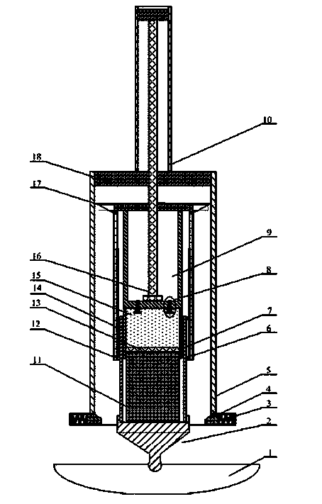
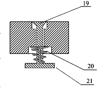
[0045] now refer to Figure 1-2 The embodiment of the built-in retractable landing buffer mechanism provided by the present invention is described in detail. The built-in retractable landing buffer mechanism mainly includes a first-stage piston cylinder 6 , a second-stage piston cylinder 7 , a third-stage piston cylinder 5 and a fourth-stage piston cylinder 10 . The fourth-stage piston cylinder 10 is placed above the thir...


PUM


Abstract

The invention provides a built-in extension-type landing buffering mechanism which comprises a first stage piston cylinder, a second stage piston cylinder, a third stage piston cylinder and a fourth stage piston cylinder. An air cavity connected with the top of the first stage piston cylinder is formed in the first stage piston cylinder, an oil cavity is formed in the lower end of the air cavity, and an overflow valve is arranged between the air cavity and the oil cavity. An opening is formed in the upper end of the second stage piston cylinder, the second stage piston cylinder is arranged in the first stage piston cylinder, the lower end of the second stage piston cylinder is connected to a buffering component, and a first buffering material is arranged in the second stage piston cylinder. The first stage piston cylinder and the second stage piston cylinder are located in the third stage piston cylinder, and can move up and down and be locked inside the third stage piston cylinder. The fourth stage piston cylinder is connected to the top of the third stage piston cylinder, a push rod is arranged in the fourth stage piston cylinder, and the lower end of the push rod is arranged on the bottom of the inner portion of the air cavity. According to the built-in extension-type landing buffering mechanism, an oil-air buffering mode is adopted, quite high impact energy can be absorbed, the built-in extension-type landing buffering mechanism can be matched with aluminum honeycomb crushing energy absorption at the same time, and the buffering effect is more efficient. In addition, the built-in extension-type landing buffering mechanism further has the function of unfolding and locking, and can be used repeatedly.

Description

technical field [0001] The invention relates to the technical field of buffer mechanism design, in particular to a reusable vertical take-off and landing built-in retractable landing buffer mechanism for aircraft. [0002] Background technique [0003] The design of the landing buffer mechanism is of great significance to the safety of the structure. Generally, the landing buffer mechanism used for the vertical take-off and landing of the aircraft is composed of two separate parts: the deployment locking device and the landing buffer device. The independent design of the deployment locking device and the landing buffer device will cause defects such as reduced reliability of the overall mechanism and increased weight. The landing buffer mechanism is the key and core component of the soft lander of the aircraft. The selection and design of the buffer and energy-absorbing components is the key to achieving a stable, reliable and safe soft landing. Its main function is to abs...

Claims


Application Information

Patent Timeline
IPC IPC(8): B64D45/04
Inventor 林轻康志宇徐大富盛英华赵启龙江晟
Owner SHANGHAI AEROSPACE SYST ENG INST
Why Eureka
Try Eureka