Pneumatic rotary feeding device

A feeding device and pneumatic technology, applied in the field of pneumatic rotary feeding device, can solve problems such as damage to the motor and difficulty of swinging the pendulum rod quickly and so on.

Inactive Publication Date: 2014-03-26
CHONGQING CHENGSHUO TECH
View PDF0 Cites 4 Cited by
  • Summary
  • Abstract
  • Description
  • Claims
  • Application Information

AI Technical Summary

Problems solved by technology

However, it is difficult for the pendulum driven by the motor to swing quickly, and it

Method used


Image

  • Pneumatic rotary feeding device

Examples


Embodiment Construction

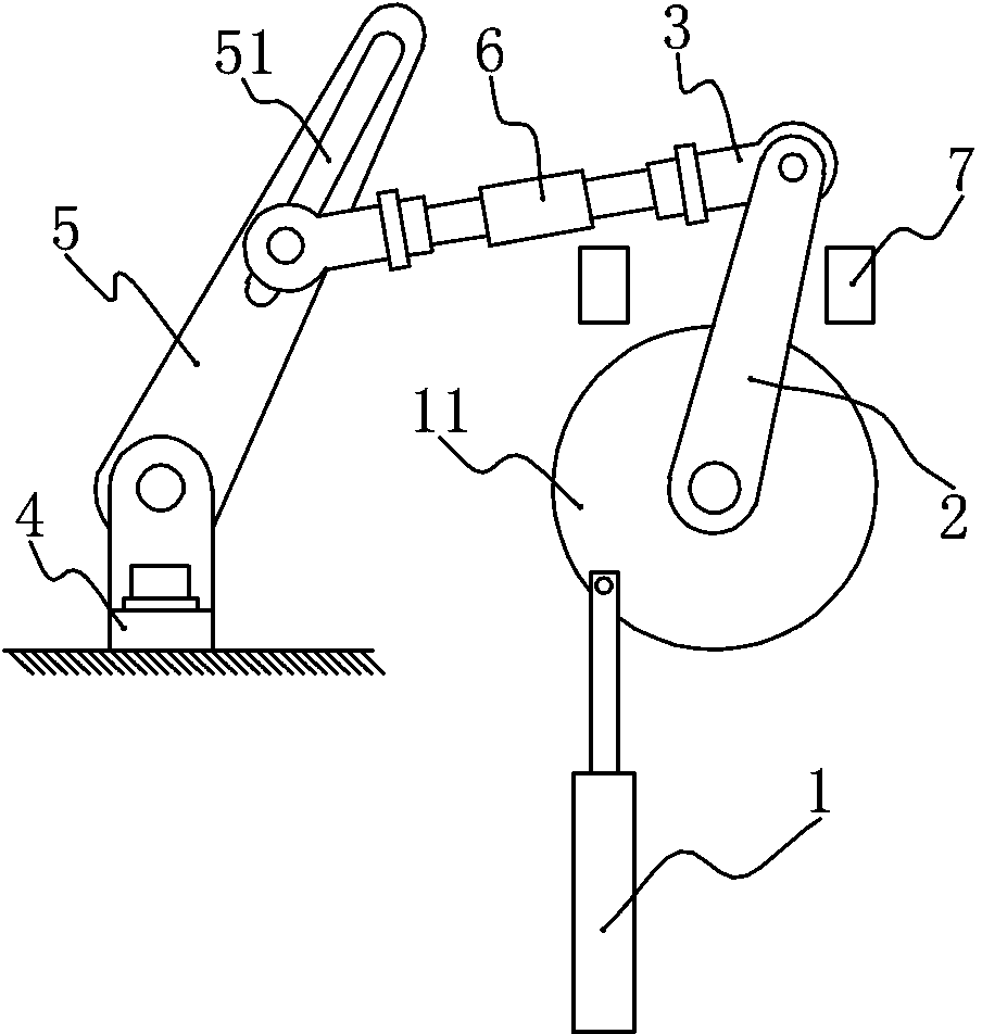
[0012] Such as figure 1 As shown, the pneumatic rotary feeding device of the present invention includes a vertical support, on which a cylinder 1 is fixed, and the piston rod of the cylinder 1 is eccentrically hinged on the rotary disk 11, and the rotating shaft of the rotary disk 11 is the same as Axle fixed a rotating rod 2. The free end of the rotating rod 2 is fixedly connected with a connecting rod 3, and the connecting rod 3 is divided into a hinged end and a sliding end. Also be provided with a fixed seat 4 on the support, on the fixed seat is hinged with a fork 5, the middle section of the fork 5 is provided with a chute 51, and the sliding end of the connecting rod 3 is fixed in the chute 51. In addition, the middle section of the connecting rod 3 is provided with a loose bolt 6, which is a through threaded pipe, and the threads at both ends of the threaded pipe are in the opposite direction; the connecting rod 3 includes two threaded rods, and the two threaded rods ...


PUM


Abstract

The invention discloses a pneumatic rotary feeding device which comprises a support. A cylinder is fixed onto the support, a piston rod of the cylinder is eccentrically hinged onto a rotary plate, and a rotary rod is coaxially fixed onto a rotary shaft of the rotary plate; a connecting rod is fixedly connected with a free end of the rotary rod and is divided into a hinge end and a slide end; a fixing seat is further arranged on the support, a swing rod for conveying workpieces is hinged onto the fixing seat, a slide groove is formed in the middle section of the swing rod, and the slide end of the connecting rod is fixed into the slide groove. The pneumatic rotary feeding device has the advantages that the rotary plate is driven by the cylinder to swing in a reciprocating manner, and the rotary rod fixed onto the rotary plate can be driven to swing in a reciprocating manner; the rotary rod is hinged to the connecting rod, and the slide end of the connecting rod is fixed into the slide groove in the swing rod, so that the swing rod can be driven by the connecting rod to swing in a reciprocating manner, and a swinging angle of the swing rod can be larger than a swinging angle of the rotary rod.

Description

technical field [0001] The invention relates to a feeding device, in particular to a pneumatic rotary feeding device. Background technique [0002] The swing mechanism is a common mechanical structure, which is widely used in various mechanical structures. A general swing mechanism is driven by a motor, and the motor drives its rotation to realize the reciprocating swing process. However, it is difficult for the pendulum driven by the motor to swing quickly, and it cannot stay at the maximum position for a long time, otherwise the motor will be damaged. Contents of the invention [0003] The object of the present invention is to provide a pneumatic rotary feeding device, which abandons the traditional motor-driven swing mechanism and has the advantage of fast swing speed. [0004] In order to achieve the above object, the technical solution of the present invention is: a pneumatic rotary feeding device, including a bracket, a cylinder is fixed on the bracket, the piston ...

Claims


Application Information

Patent Timeline
IPC IPC(8): B65G25/12
Inventor 李清芬
Owner CHONGQING CHENGSHUO TECH
Why Eureka
Try Eureka