
Construction machine with material conveying system

A technology of construction machinery and transmission system, applied in the field of construction machinery, to achieve the effects of optimized preparation, precise adjustment, and increased transmission volume

Active Publication Date: 2014-03-26
JOSEPH VOEGELE AG
View PDF10 Cites 0 Cited by
  • Summary
  • Abstract
  • Description
  • Claims
  • Application Information

AI Technical Summary

Problems solved by technology

As long as the first flight of the screw is filled with material, no other material can be conveyed into this flight from above, whereby the desired mixing effect does not occur

Method used


Image

  • Construction machine with material conveying system
  • Construction machine with material conveying system
  • Construction machine with material conveying system

Examples


Embodiment Construction

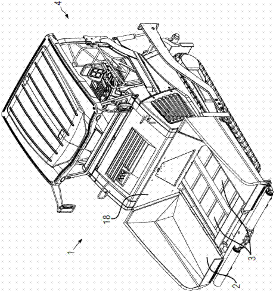
[0034] figure 1 A construction machine 1 is shown with a material hopper 2 for mixtures or generally for bulk materials. A downstream conveying system 3 (in this case two scraper belts) extends in the central part of the hopper 2 . The downstream transport system 3 is used to transport the mixture under the cab 4 to the paving site.

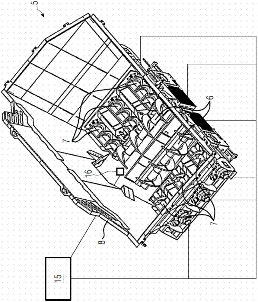
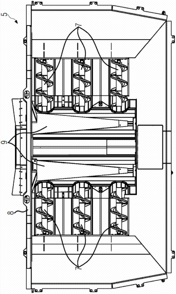
[0035] figure 2 A material transfer system 5 possibly arranged in the hopper 2 is shown. The material conveying system comprises two longitudinal conveying screws 6 , six transverse conveying screws 7 and a rear wall 8 . In the installed state, said rear wall 8 is oriented towards the rear wall 18 of the hopper. Such as figure 2 As can be seen in , the transfer screws 6, 7 cover the entire bottom area of ​​the material transfer system. Since the conveying screws 6, 7 can be operated independently of each other, the individual material flows from the various parts of the material conveying system 5 can be controlled in a desired manner. For...


PUM


Abstract

A construction machine (1) according to the disclosure comprises a material hopper (2) for receiving bulk material. Moreover, the construction machine (1) includes a material conveying system (5) for conveying bulk material. The material conveying system (5) comprises at least one conveying screw (6) in the area of the hopper (2). A gap (9) extends underneath the at least one conveying screw (6), and the gap (9) has a cross section that varies in a conveying direction of the at least one conveying screw.

Description

technical field [0001] The invention relates to a construction machine with a material transport system. Background technique [0002] A bituminous mixture is produced in the mixing system. This is done by heating the stone chips in a converter and then feeding the stone chips into a mixer. In this mixer, hot bitumen is additionally injected and mixed with hot stone chips. The mixture is then temporarily stored in hot silos or transported by truck directly to the road construction site. The asphalt mix leaves this mixer at a high and very uniform temperature. The mixture cools in an inhomogeneous manner due to subsequent storage and especially due to transport. Typically, the asphalt mix still has a very high core temperature when it is delivered to the road construction site, but the edge regions have cooled considerably. Then there is no longer a mixture with a uniform temperature. A uniform temperature distribution of the mixture is one of the most important paramet...

Claims


Application Information

Patent Timeline
Patent Type & Authority Applications(China)
IPC IPC(8): E01C19/08
CPCE01C19/48E01C19/002
Inventor M·布施曼S·费克森L·高达德
Owner JOSEPH VOEGELE AG
Learn More