A device and method for adjusting the size of the top mold system hanger

A hanger and system technology, which is applied to the scaffolding of house structure support, house structure support, house structure support, etc., can solve the problems of less turnover times of hangers, inability to change freely, and high difficulty, so as to achieve a good working environment and save engineering The effect of increasing time and versatility

Active Publication Date: 2015-11-04
NO 1 CONSTR ENG CO LTD OF CHINA CONSTR THIRD ENG BUREAU CO LTD
View PDF5 Cites 0 Cited by
  • Summary
  • Abstract
  • Description
  • Claims
  • Application Information

AI Technical Summary

Problems solved by technology

[0002] At present, sectioned steel climbing frames (or hangers) are generally used in the construction of core tube structures of super high-rise buildings. The sectioned steel climbing frames used in the construction of yin and yang corners generally adopt a fixed cantilever method. ) changes; if the size of the yin and yang corners changes greatly, the section steel scaffolding must be replaced or modified as a whole.
The commonly used stereotyped hangers are of stereotyped size in floor height and horizontal width. The end of the stereotyped hanger cannot be freely expanded and contracted, that is, the overall size of the rack body cannot be freely changed with the change of the size of the yin and yang corners of the building. The versatility is not strong. Need Customized according to the peripheral dimensions and storey heights of different buildings, the number of rotations of the hangers in use is small, resulting in an increase in the cost of using the fixed hangers

Method used


Image

  • A device and method for adjusting the size of the top mold system hanger
  • A device and method for adjusting the size of the top mold system hanger
  • A device and method for adjusting the size of the top mold system hanger

Examples


Embodiment Construction

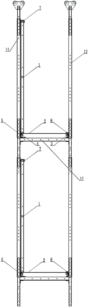
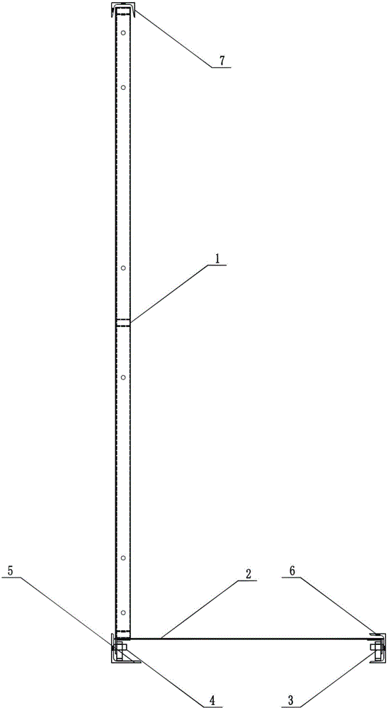
[0032] In order to better understand the technical solution of the present invention, the present invention will be further described below through examples and accompanying drawings.

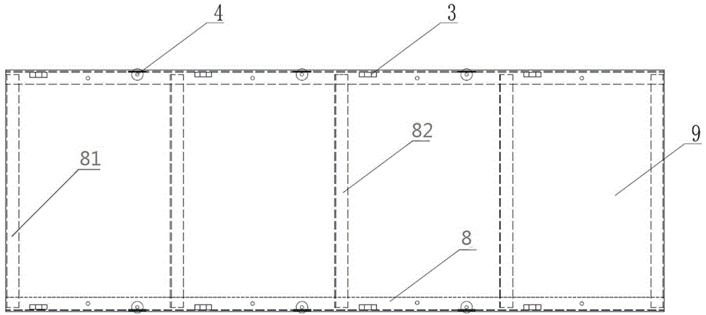
[0033] A device for adjusting the size of the top mold system hanger, such as figure 1 and figure 2 As shown, it includes a facade protective net frame 1, a moving plate 2, a guide angle steel 5, a first guide channel steel 6 and a second guide channel steel 7; Vertical fixed connection, the left and right ends of the lower surface of the moving plate 2 are provided with a plurality of vertical bearings 3 and horizontal bearings 4, and the plurality of vertical bearings 3 and horizontal bearings 4 are arranged along the length direction of the moving plate 2; Angle steel 5 and the first guide channel steel 6 are respectively fixed on the left and right ends of the base plate 13 of hanger 12, and the opening of guide angle steel 5 is upwards, and the opening of the first guide channel steel 6 ...


PUM


Abstract

The invention relates to a device and method for adjusting the size of a top die system hanging rack. The device for adjusting the top die system hanging rack comprise a vertical face protecting net frame, a movable plate, guide angle steel, first guide channel steel and second guide channel steel. The lower end of the vertical face protecting net frame is vertically and fixedly connected with the left end of the movable plate, and the left end and the right end of the lower surface of the movable plate are respectively provided with a plurality of vertical bearings and horizontal bearings. The guide angle steel and the first guide channel steel are arranged at the left end and the right end of a bottom plate of the hanging rack respectively. The second guide channel steel is arranged at the upper end of a vertical rod of the hanging rack. The left end and the right end of the movable plate are placed in an opening of the guide angle steel and an opening of the first guide channel steel respectively. The upper end of the vertical protecting net frame is placed in an opening of the second guide channel steel. According to the device and method for adjusting the size of the top die system hanging rack, the vertical face protecting net frame and the movable plate can slide along the guide angle steel and the first guide channel steel, so that the size of a rack body of the hanging rack is adjusted freely, and the hanging rack can be adapted to the size variation of a building core tube.

Description

technical field [0001] The invention relates to a core tube construction hanger for a building with an outer frame inner tube structure, and more specifically relates to a device and method for adjusting the size of the top form system hanger. Background technique [0002] At present, sectioned steel climbing frames (or hangers) are generally used in the construction of core tube structures of super high-rise buildings. The sectioned steel climbing frames used in the construction of yin and yang corners generally adopt a fixed cantilever method. ) changes; if the size of the yin and yang corners changes greatly, the section steel scaffolding must be replaced or modified as a whole. The commonly used stereotyped hangers are of stereotyped size in floor height and horizontal width. The end of the stereotyped hanger cannot be freely expanded and contracted, that is, the overall size of the rack body cannot be freely changed with the change of the size of the yin and yang corner...

Claims


Application Information

Patent Timeline
Patent Type & Authority Patents(China)
IPC IPC(8): E04G3/28E04G21/00
Inventor 楼跃清寇广辉童涛刘洪海杨斌苏浩
Owner NO 1 CONSTR ENG CO LTD OF CHINA CONSTR THIRD ENG BUREAU CO LTD
Why Eureka
Try Eureka