
Main part device of shaking force hydraulic engine

An engine and hydrodynamic technology, applied in the direction of machines/engines, mechanisms for generating mechanical power, mechanical equipment, etc., can solve problems such as rare discoveries, and achieve the effects of strong practicability, stable performance, and convenient manufacture

Inactive Publication Date: 2014-03-26
陈明 +1
View PDF0 Cites 1 Cited by
  • Summary
  • Abstract
  • Description
  • Claims
  • Application Information

AI Technical Summary

Problems solved by technology

[0002] At present, in the known technology, there has not yet been found an engine that relies on high-level kinetic energy to perform circular motion and work. Most of them are in the experimental stage, and few products that can form industrialization have been found.

Method used


Image

  • Main part device of shaking force hydraulic engine
  • Main part device of shaking force hydraulic engine
  • Main part device of shaking force hydraulic engine

Examples


Embodiment Construction

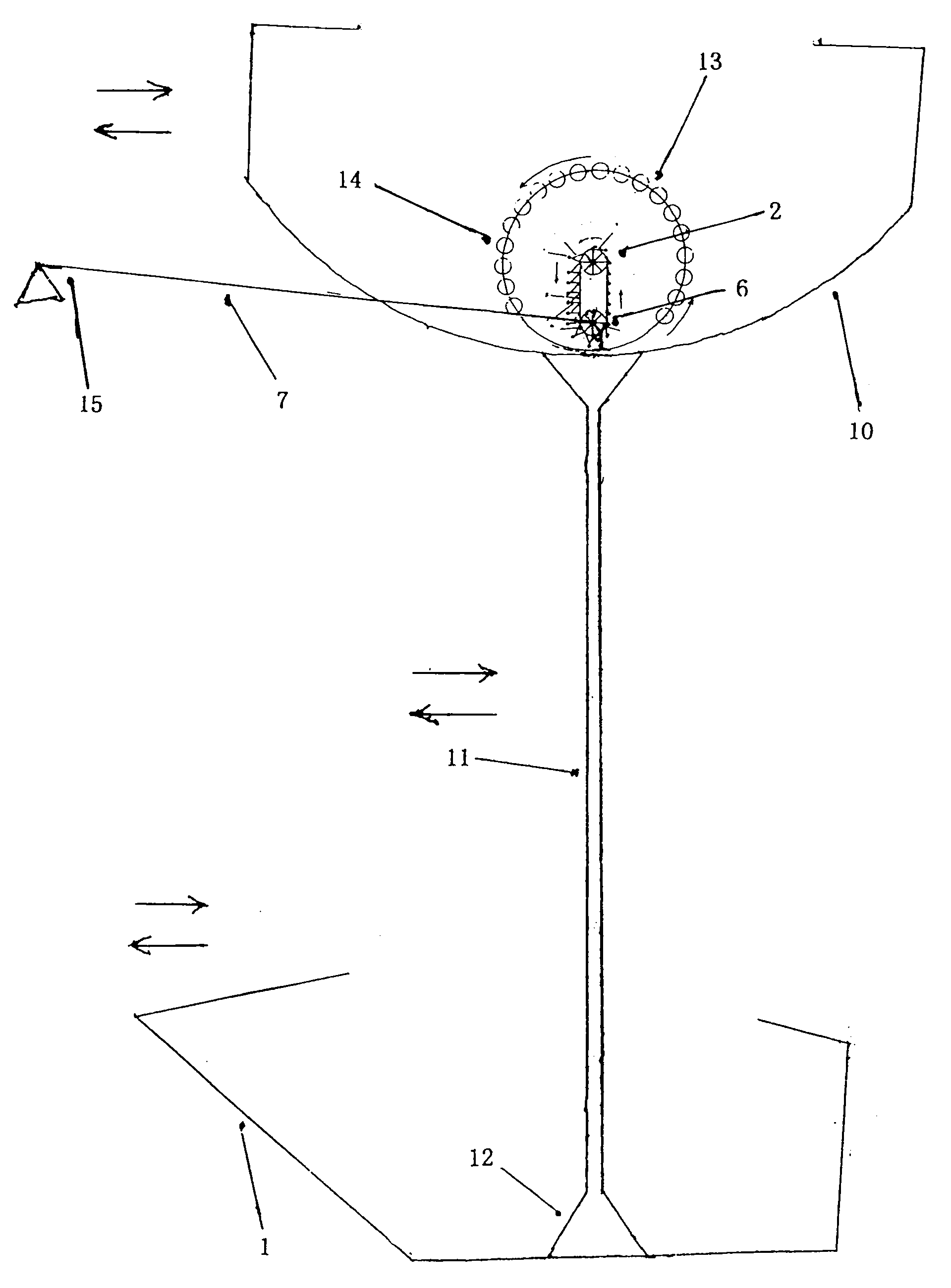
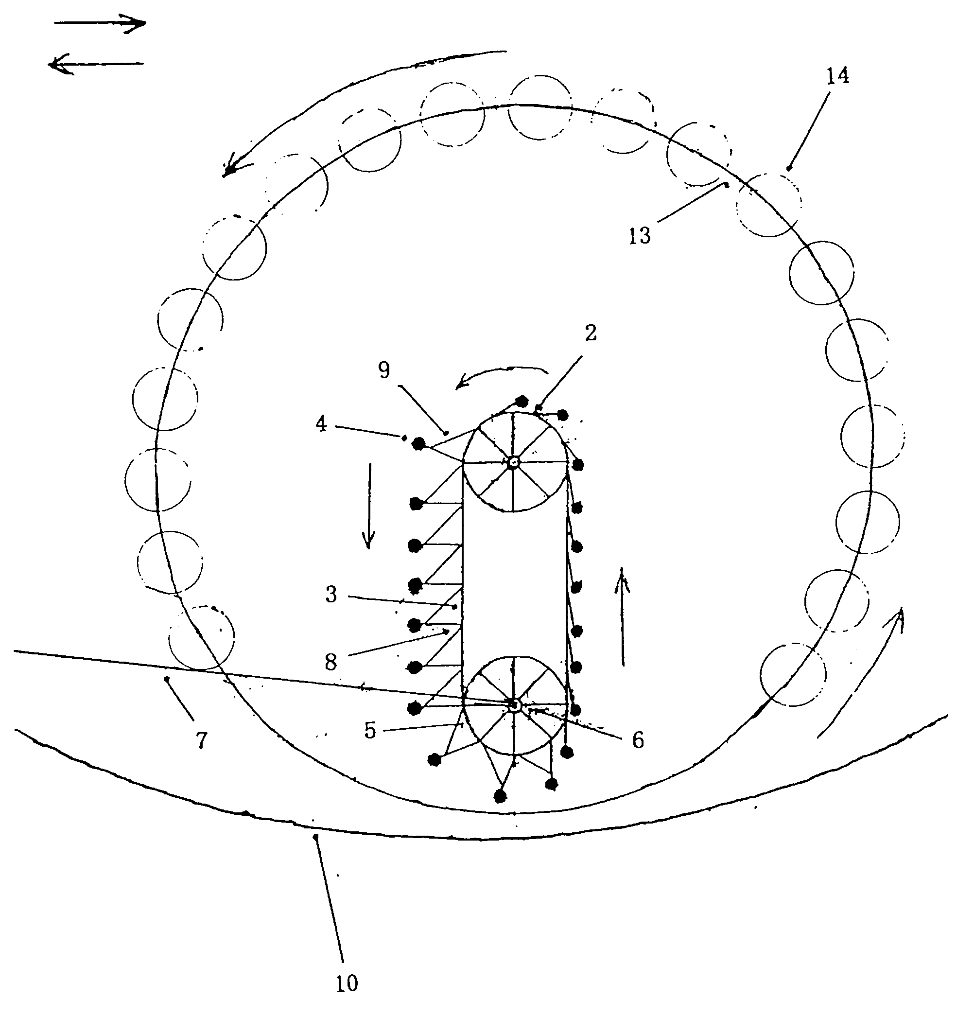
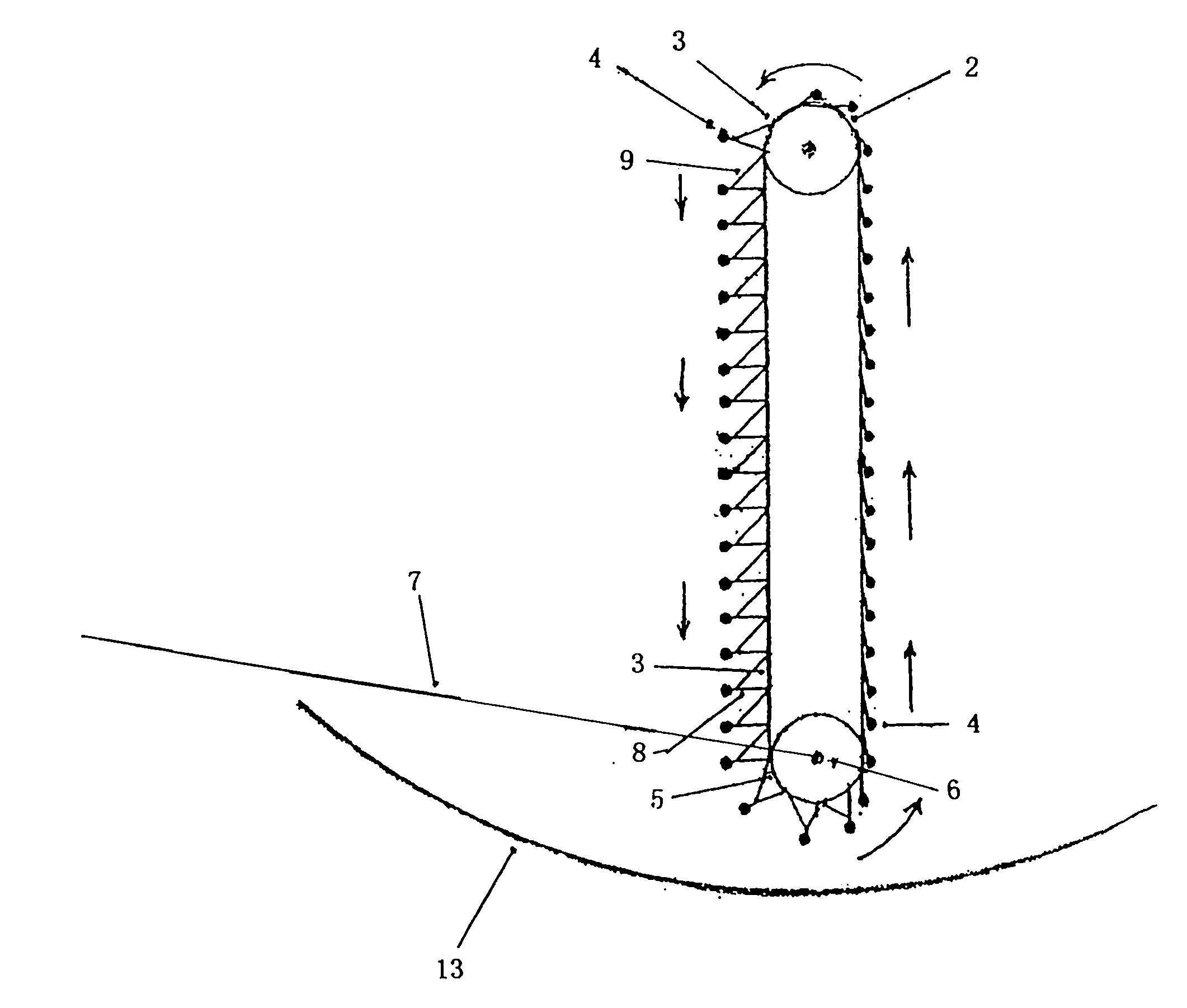
[0013] exist figure 1 Among them, the hull pile base (12) is set on the undulating pontoon (1) to connect, and the high-position elastic shaking long rod (11) is set on the hull pile base (12) to connect, and the high-position elastic shaking long rod (11) is connected to the elevated arc shaking The track is rotatable (10) connected, and the bull wheel (13) with many small bearings (14) is arranged on the elevated arc swing track (10), and the load wheel (2) is connected in the middle of the bull wheel (13). ), the middle of the pay piece wheel central axis (6) is connected with a section of superlong drag cable (7). The bull wheel (13) is connected with many small bearings (14) in rolling contact. Many small bearings (14) are connected with the rolling contact of the elevated arc swinging track (10), and superlong pull cables (7) are set on the anchor piles (15) to connect.

[0014] exist figure 2 middle, figure 2 and figure 1 The part is the same, many small bearings...


PUM


Abstract

A main part device of a shaking force hydraulic engine comprises a fluctuation floating pontoon, a pontoon body pile base, a load wheel, an annular chain belt, a load weight, a supporting rod, a pull cable, an accessory wheel, an accessory wheel center shaft, a super long pull cable, an elevated arc-shaped shaking rail, a high elastic shaking long rod, a small bearing, a large wheel and an anchor pile; the fluctuation floating pontoon is connected with the pontoon body pile base; the load wheel is connected with the annular chain belt; the load weight is connected with the supporting rod, the pull cable and the annular chain belt; the accessory wheel is connected with the annular chain belt; the accessory wheel center shaft is connected with the super long pull cable; the elevated arc-shaped shaking rail is in rotating connection with the high elastic shaking long rod which is connected with the pontoon body pile base; the small bearing is connected with the large wheel which is connected with the load wheel; the super long pull cable is connected with the anchor pile. The main part device of the shaking force hydraulic engine is suitable for movement in the water.

Description

Technical field [0001] The invention relates to an unbalanced load-bearing hydrodynamic machine with a high level of renewable energy that is prone to shaking and unbalanced load-bearing, an energy conversion device with an unbalanced load-bearing that is easy to generate shaking force at a high level, especially The utility model relates to a main component device of a water-driven motor with shaking force. Background technique [0002] At present, in the known technology, there is no engine that relies on the high position to generate kinetic energy to carry out cyclical motion and work. Most of them are in the test stage, and few products that can form industrialization have been found. Contents of the invention [0003] At present, it is adopted: the object is easy to shake to generate kinetic energy after being unbalanced, and the engine that is easy to generate shaking force at a high position and moves continuously, and the shaking force in the river, sea, and lake ...

Claims


Application Information

Patent Timeline
Patent Type & Authority Applications(China)
IPC IPC(8): F03G7/10
Inventor 陈明
Owner 陈明
Learn More