Supercharge Your Innovation With Domain-Expert AI Agents!

Prismatic rod vacuum pump

A vacuum pump and prism technology, applied in the direction of pumps, pump components, rotary piston pumps, etc., can solve the problems of easy damage to piston rings and air valves, non-green environmental protection, high operation and maintenance costs, and improve the sealing effect. Lubrication effect, effect of increasing contact area

Active Publication Date: 2014-03-26
ZIBO JINGYAO VACUUM EQUIP
View PDF10 Cites 1 Cited by
  • Summary
  • Abstract
  • Description
  • Claims
  • Application Information

AI Technical Summary

Problems solved by technology

On the one hand, reciprocating vacuum pumps with oil will produce a large amount of oil and gas pollution when exhausting, which does not meet the requirements of environmental protection; The piston ring and air valve assembly are easily damaged, coupled with the complex transmission mechanism, resulting in poor operating stability of the pump, many wearing parts, and relatively high operation and maintenance costs
[0005] There is also a Roots vacuum pump with a simple structure, which relies on the rotation of the Roots rotor to transport gas, but it has no internal compression function during the process of transporting gas, that is, it cannot pressurize the gas through compression, so that the gas at the exhaust port can be discharged smoothly. To the atmosphere, it can only be used as an auxiliary vacuum pump

Method used


Image

  • Prismatic rod vacuum pump
  • Prismatic rod vacuum pump
  • Prismatic rod vacuum pump

Examples


Embodiment Construction

[0046] The present invention will be further described in detail below in conjunction with the accompanying drawings and specific embodiments.

[0047] The present invention is named as a rib-rod vacuum pump because of its rotor with rib-rod structure.

[0048] In the present invention, the length direction of the rotor is defined as the front-rear direction, the side close to the pump cavity 7 is defined as the inner side, and the side far away from the pump cavity 7 is defined as the outer side accordingly.

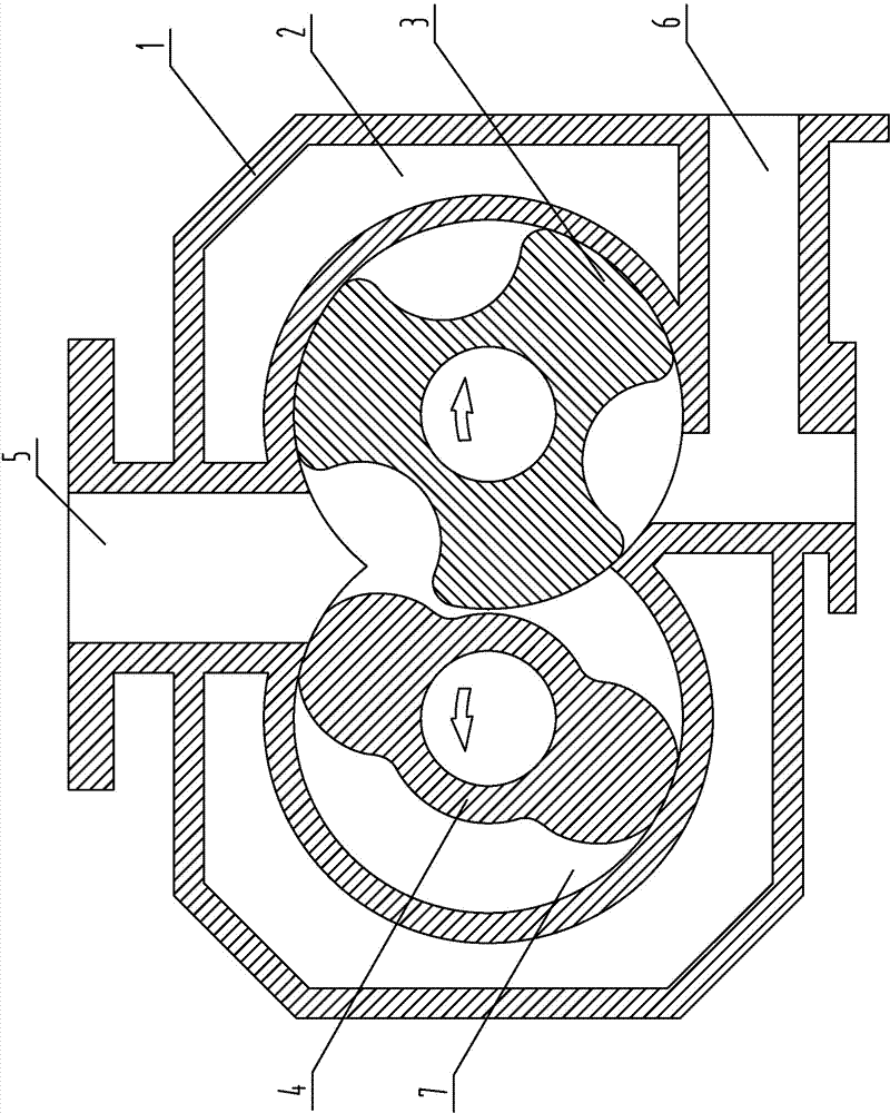
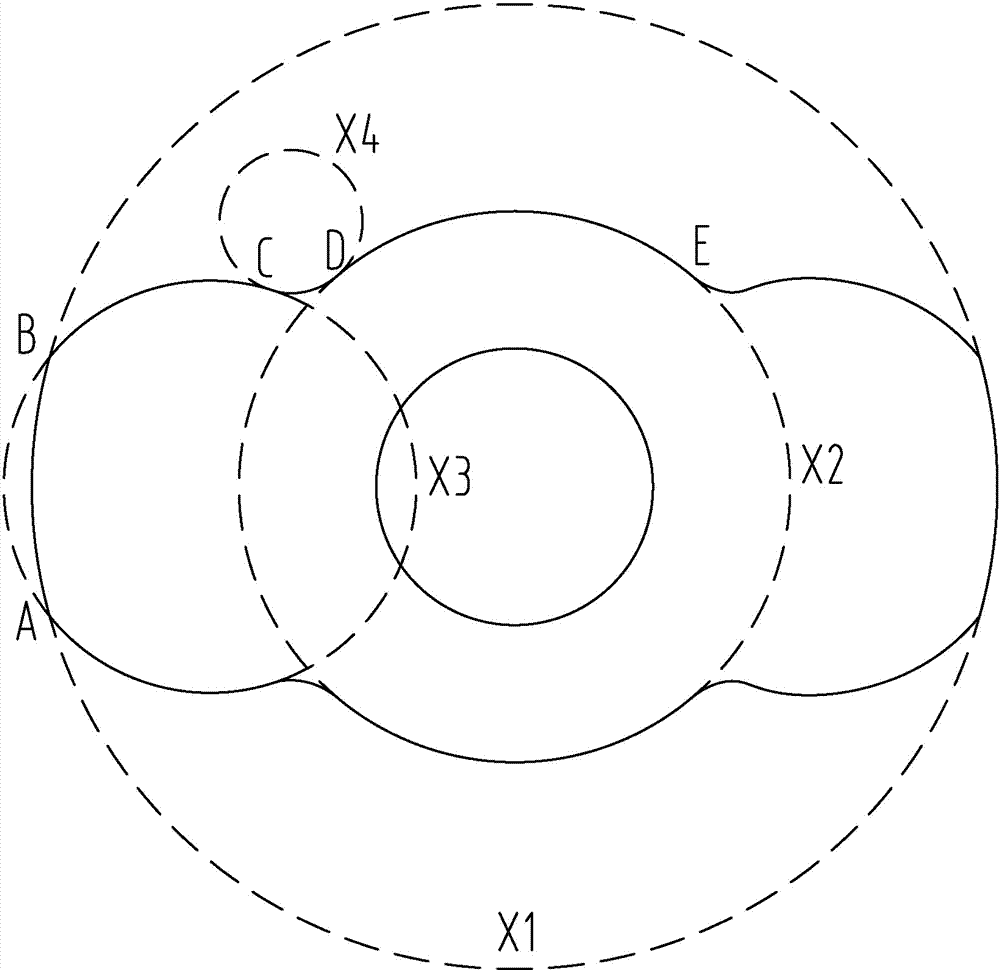
[0049] Such as figure 1 As shown, the pump casing 1 of the present invention is provided with a "∞" type pump chamber 7, and the rotor installed in the pump chamber 7 is divided into a main rotor 4 and an auxiliary rotor 3 whose axes are parallel to each other. The two convex teeth of the cloth, the profiles of the convex teeth are parallel to the axis of the main rotor 4, such as figure 2 As shown, the profile line of the end surface is a symmetrical structure, whic...


PUM

PropertyMeasurementUnit
Radius rangeaaaaaaaaaa

Abstract

The invention discloses a prismatic rod vacuum pump, which belongs to the technical field of the variable capacity vacuum equipment. The prismatic rod vacuum pump comprises a rotor and a pump case, wherein a thwartwise-8-shaped pump cavity is arranged in the pump case, and the rotor is installed in the pump cavity. The prismatic rod vacuum pump is characterized in that the rotor is divided into a main rotor and an auxiliary rotor of which the axes are mutually parallel; the main rotor is provided with two double wedges which are circumferentially evenly distributed; the molded surfaces of the double wedges are parallel with the axis of the main rotor; the auxiliary rotor is provided with three grooves which are circumferentially evenly distributed; the molded surfaces of the groves are parallel with the axis of the auxiliary rotor; the double wedges and the grooves are mutually meshed; the revolving speed ratio of the main rotor to the auxiliary rotor is 3 / 2. According to the prismatic rod vacuum pump disclosed by the invention, the volume of the pump cavity can be changed by the rotation of the main rotor and the auxiliary rotor, the compression of conveyed gas is realized, the volume efficiency can be improved, and the compression ratio is enabled to reach 40%. Meanwhile, the residual gas of each exhaust is reduced to 10%. In addition, no waste water or gas is generated in the working process.

Description

technical field [0001] The invention belongs to the technical field of variable capacity vacuum equipment, and in particular relates to a ribbed vacuum pump. Background technique [0002] With the continuous development of vacuum technology, its application field has been continuously expanded, and it has been widely used in various industrial fields such as machinery, chemical industry, pharmaceuticals, food, papermaking, energy, and aerospace. However, the principle and structure of vacuum pumps used in many fields today are almost the same as those of 30 years ago, without any fundamental changes. Among them, water ring vacuum pumps, water jet vacuum pumps and reciprocating vacuum pumps are widely used in the field of low vacuum. [0003] Water ring vacuum pumps and water jet vacuum pumps need water as the working medium. On the one hand, their performance depends on the saturated vapor pressure of water. Therefore, the temperature of the working water directly affects t...

Claims


Application Information

Patent Timeline
IPC IPC(8): F04C18/14F04C25/02F04C29/02F04C29/00F04C29/04
Inventor 徐黎明
Owner ZIBO JINGYAO VACUUM EQUIP
Features
  • R&D
  • Intellectual Property
  • Life Sciences
  • Materials
  • Tech Scout
  • Unparalleled Data Quality
  • Higher Quality Content
  • 60% Fewer Hallucinations
Learn More