Light source with quantum dots and manufacturing method and application of light source with quantum dots

A production method and technology of quantum dots, which are applied in electric light sources, optics, nonlinear optics, etc., can solve the problems of high cost of quantum dot production, uneconomical benefits, etc., to save resources, save quantity, and increase the angle of light output. Effect

Inactive Publication Date: 2014-03-26
TCL CHINA STAR OPTOELECTRONICS TECH CO LTD
View PDF5 Cites 18 Cited by
  • Summary
  • Abstract
  • Description
  • Claims
  • Application Information

AI Technical Summary

Problems solved by technology

However, due to the high cost of quantum dot fabrication, it is not economical to use a large number of quantum dot bars in a backlight

Method used


Image

  • Light source with quantum dots and manufacturing method and application of light source with quantum dots
  • Light source with quantum dots and manufacturing method and application of light source with quantum dots
  • Light source with quantum dots and manufacturing method and application of light source with quantum dots

Examples


Embodiment 1

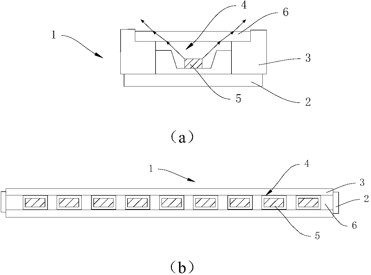
[0043] Figure 4 The figure shows the short-axis cross-sectional structure of the light-emitting source 40 using quantum dots provided in this embodiment. The light emitting source 40 includes: a substrate 41 on which a light bar 43 and a light mixing body 42 arranged around the light bar 43 are installed. Wherein, the light bar 43 may specifically be composed of an LED light 44 and a circuit board thereof. A quantum dot bar 45 is erected on the top of the light mixing body 42, and the emitted light of the light bar 43 is refracted by the quantum dot bar 45 and then emerges. Surface) is a curved surface, so that the emitted light is further diverged and emitted through the quantum dot bar 45, and the light emitting angle can reach 150°-160°, which effectively increases the light emitting angle of the light source.

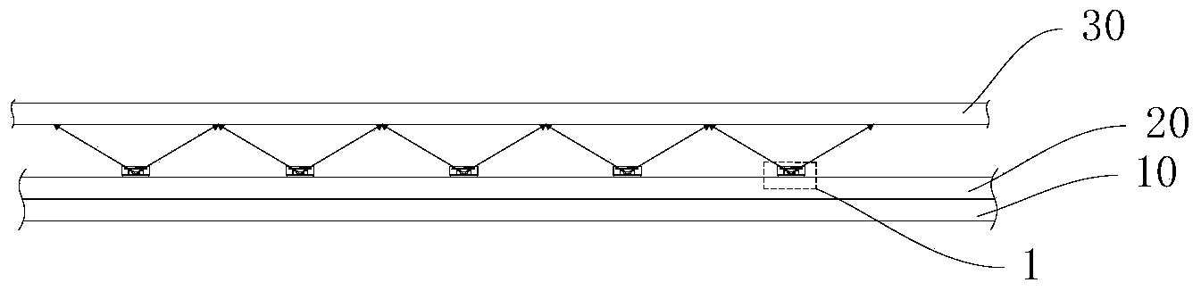
[0044] By assembling this light source 40 into an existing direct-lit backlight source, obvious beneficial effects can be obtained. see image 3 As shown, the ...

Embodiment 2

[0050] This embodiment is a further improvement or change to the quantum dot bar structure and manufacturing method. The light emitting surface of the quantum dot bar in this embodiment has concave grooves. For example, if Figure 7 As shown, a groove 48 can be formed on the top of the quantum dot bar 45a obtained in Example 1, so that the obtained light-emitting surface is not a smooth transition arc surface, and a new quantum dot bar 45c is formed. Further, in order to uniformly disperse the emitted light from the light bar (not shown in the figure) from the center, the groove 48 preferably corresponds to the light emitting center of the light bar.

[0051] The above-mentioned quantum dot bar 45c can be obtained by the first manufacturing method in Embodiment 1, and the obtained quantum dot bar light path diagram is as follows Figure 7 As shown, the purpose of the invention of increasing the light emitting angle of the light emitting source can also be achieved.

[0052]...

Embodiment 3

[0054] In this embodiment, the structure of the quantum dot bar provided in Example 2 is further improved, and the shape of the groove on the light-emitting surface of the quantum dot bar can also be changed along with the change of the curved surface pattern of the light-emitting surface of the quantum dot bar. Such as Figure 9 As shown, the short-axis section of the light-emitting surface of the quantum dot bar 45e in this embodiment is in the shape of double arches juxtaposed left and right. In order to disperse the emitted light from the light bar (not shown in the figure) evenly from the center, the juxtaposed arches are arranged symmetrically, and the groove 48a formed by the double arches corresponds to the light emitting center of the light bar.

[0055] Similarly, the quantum dot bar 45e of this embodiment can be obtained by the first preparation method provided in Embodiment 1, and its structure and optical path diagram are as follows Figure 9 shown.

[0056] It ...


PUM

PropertyMeasurementUnit
diameteraaaaaaaaaa
refractive indexaaaaaaaaaa

Abstract

The invention relates to the technical field of liquid crystal display, in particular to a structural improvement on a directly-down-type backlight source, and provides a light source with quantum dots. The light source comprises a substrate, a lamp bar and light mixing bodies arranged around the lamp bar are installed on the substrate, quantum dot stick blocks are arranged at the tops of the light mixing bodies, light emitted by the lamp bar is refracted by the quantum dot stick blocks to go out, and the light outgoing faces of the quantum dot stick blocks are curved surfaces. The invention further provides a manufacturing method of the quantum dot stick blocks and the novel directly-down-type backlight source assembled with the quantum dot stick blocks. According to the light source with the quantum dots, due to the fact that the light outgoing faces of the quantum dot stick blocks are the curved surfaces through the structural improvement on the quantum dot stick blocks, the light diffusion angle formed after the light emitted by the lamp bar passes through the quantum dot stick blocks is increased, and finally the light outgoing angle of the light source is increased.

Description

technical field [0001] The invention relates to the technical field of liquid crystal displays, in particular to the improvement of a backlight source structure. Background technique [0002] Quantum Dot (QD), also known as nanocrystal, is a nanoparticle composed of II-VI or III-V elements. The particle diameter of quantum dots is generally between 1 and 10 nm. Since electrons and holes are quantum-confined, the continuous energy band structure becomes a discrete energy level structure with molecular characteristics, and can emit fluorescence after being excited. Based on quantum effects, quantum dots have broad application prospects in solar cells, light-emitting devices, optical biomarkers and other fields. [0003] The optoelectronic properties of quantum dots are closely linked to their size and shape. The study found that the energy bandgap of quantum dots is inversely proportional to the size, that is, the quantum dots are smaller in size and wider in energy bandgap,...

Claims


Application Information

Patent Timeline
Patent Type & Authority Applications(China)
IPC IPC(8): F21S8/00F21V5/08F21V13/00G02F1/13357
CPCG02F1/133606G02F1/133609G02F1/133607G02F1/133614H01L33/0083H01L33/06H01L33/483H01L33/54
Inventor 丘永元张简圣哲康志聪苏赞加
Owner TCL CHINA STAR OPTOELECTRONICS TECH CO LTD
Why Eureka
Try Eureka