Dual-fuel combustion chamber nozzle of combustion gas turbine

A gas turbine and dual-fuel technology, applied in combustion chambers, continuous combustion chambers, combustion methods, etc., can solve problems such as unfavorable flame stability, difficulty in maintaining high-efficiency combustion, and disturbing the flow field of the combustion chamber, so as to avoid the phenomenon of uneven dilution, Protects against burnout and improves combustion stability

Active Publication Date: 2014-03-26
CHINA UNITED GAS TURBINE TECH CO LTD
View PDF6 Cites 8 Cited by
  • Summary
  • Abstract
  • Description
  • Claims
  • Application Information

AI Technical Summary

Problems solved by technology

For injecting diluent, one of the methods is to use external pre-fuel dilution, but this requires the purchase of additional equipment, so it is not commonly used in engineering; when using air accompanying dilution, the diluent will block the air flow channel on the one hand, and reduce the oxidant at the same time. It is difficult to maintain high-efficiency combustion; and when the fuel is diluted, it will greatly reduce the calorific value of the fuel per unit volume, which will also make it difficult to improve the combustion efficiency; and directly injecting the diluent into the combustion zone will disturb the combustion chamber Flow field, which is not conducive to flame stability, and will also deteriorate the outlet temperature distribution

Method used


Image

  • Dual-fuel combustion chamber nozzle of combustion gas turbine
  • Dual-fuel combustion chamber nozzle of combustion gas turbine

Examples


Embodiment Construction

[0018] The principle, structure and specific implementation of the present invention will be further described below in conjunction with the accompanying drawings.

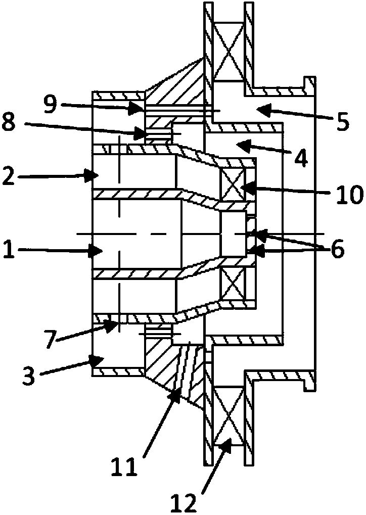
[0019] figure 1 A schematic diagram of the structural principle of a gas turbine dual-fuel combustor nozzle provided by the present invention, the nozzle includes an axial central fuel passage 1 and a peripheral axial annular fuel passage 2 coaxially arranged with the axial central fuel passage 1, and its characteristics In that: outside the peripheral axial annular fuel passage 2, a peripheral axial annular dilution gas passage 3 coaxially arranged with the axial central fuel passage 1 is also arranged; the air passage of the nozzle is also arranged coaxially with the axial central fuel passage 1, and It is divided into a first-level peripheral radial annular air channel 4 and a second-level peripheral radial annular air channel 5 .

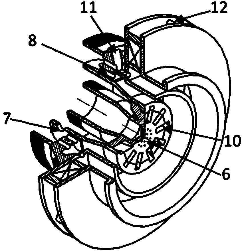
[0020] There are dense small holes 6 on the wall surface of the outlet end of ...


PUM


Abstract

The invention relates to a dual-fuel combustion chamber nozzle of a combustion gas turbine, and belongs to the technical field of combustion gas turbines. The dual-fuel combustion chamber nozzle comprises an axial center fuel channel, a peripheral axial annular fuel channel, a peripheral axial annular diluent gas channel, a first-level peripheral radial-direction annular air channel and a second-level peripheral radial-direction annular air channel, wherein the peripheral axial annular fuel channel, the peripheral axial annular diluent gas channel, the first-level peripheral radial-direction annular air channel and the second-level peripheral radial-direction annular air channel are arranged to be coaxial with the axial center fuel channel. The nozzle supplies fresh air to the head of a combustion chamber in a two-stage mode, meanwhile a diluent is divided into three plumes, one plume is supplied to fuel, one plume is supplied to first-level air, and another plume is supplied to second-level air; the ratio of the three plumes of the diluents can be adjusted according to the result of optimizing the performance of the combustion chamber, so that the sufficient air is supplied to the fuel for supporting combustion, and the good balance of efficient combustion and reduction of flame temperature is obtained; secondly, the diluents, the fuel and the air are mixed well and then enter a flame tube to take part in combustion, so that addition of the diluents does not disturb a inner flow field in the combustion chamber, and stability of combustion and good outlet temperature distribution are ensured.

Description

technical field [0001] The invention relates to a gas turbine combustor nozzle, in particular to a gas turbine low-pollution combustor nozzle capable of using dual fuels. Background technique [0002] In my country's current energy structure, thermal power generation using traditional coal-fired technology occupies the vast majority of the share. However, this traditional power generation technology has disadvantages such as low power generation efficiency, high pollutant emissions (especially NOx emissions), and high consumption of fresh water resources. As a new "green" coal combustion technology, IGCC (Integrated Gasification Combined Cycle Power Generation System) provides a new way for the clean and efficient utilization of coal. [0003] The gas turbine in the IGCC system uses the low-to-medium calorific value synthetic gas produced by the gasifier as fuel, and quickly mixes and burns with the high-pressure air delivered by the compressor in the combustion chamber. Th...

Claims


Application Information

Patent Timeline
Patent Type & Authority Applications(China)
IPC IPC(8): F23R3/38
Inventor 查筱晨张珊珊
Owner CHINA UNITED GAS TURBINE TECH CO LTD
Why Eureka
Try Eureka