Contraction type heat exchanger

A technology of heat exchangers and heat exchange tubes, applied in evaporators/condensers, lighting and heating equipment, refrigeration components, etc., can solve the problems of affecting heating effect, evaporator congestion, pressure drop sensitivity, etc.

Active Publication Date: 2014-03-26
GUANGDONG CHIGO AIR CONDITIONING
View PDF5 Cites 4 Cited by
  • Summary
  • Abstract
  • Description
  • Claims
  • Application Information

AI Technical Summary

Problems solved by technology

[0007] When the heat exchanger is an evaporator, the flow direction of the refrigerant is opposite to the change process of the refrigerant in the above-mentioned condenser, that is, the refrigerant in the evaporator is in the process of evaporating and absorbing heat, and the refrigerant changes from liquid to gas The volume gradually increases. When the evaporator is turned on, th

Method used


Image

  • Contraction type heat exchanger
  • Contraction type heat exchanger
  • Contraction type heat exchanger

Examples


Embodiment 1

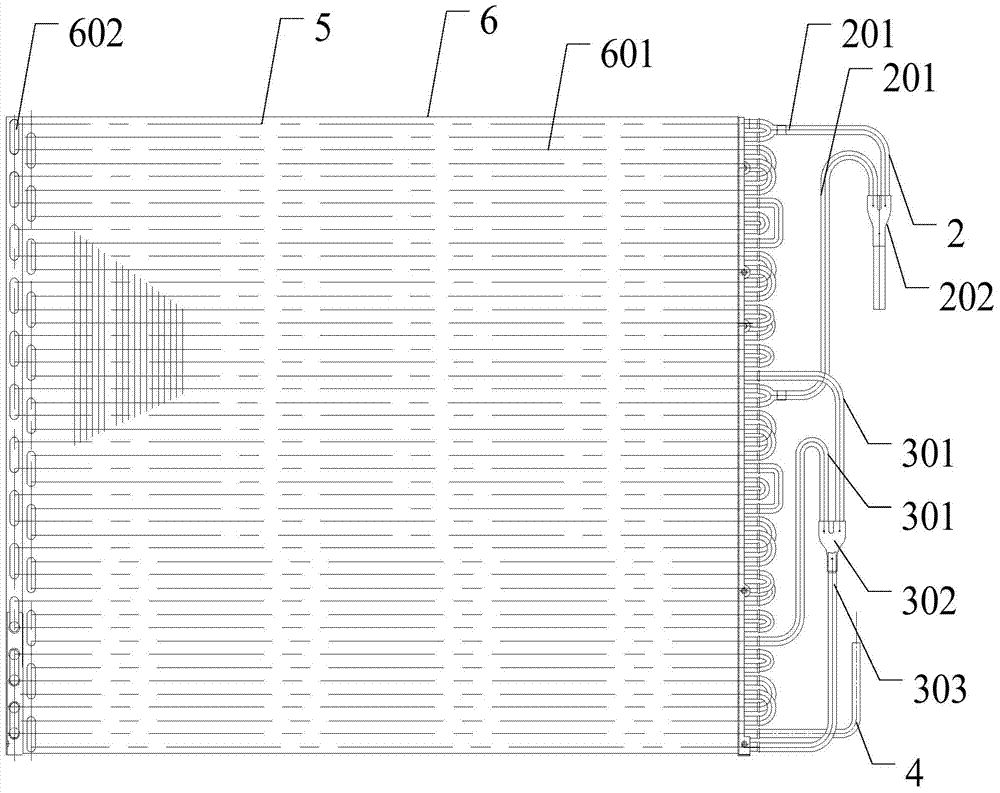
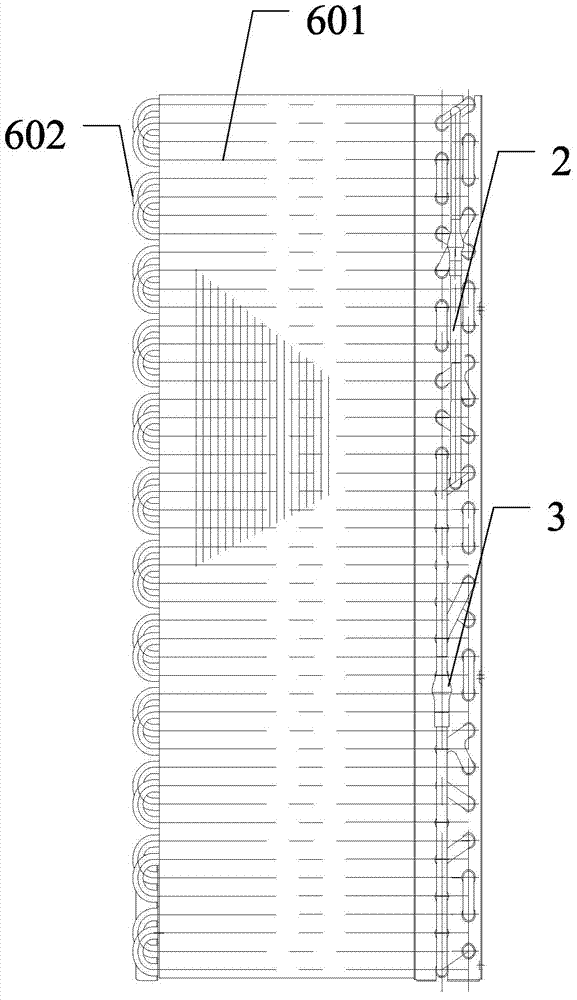
[0033] See figure 2 with image 3 , figure 2 It is a schematic diagram of the structure of a shrinkable heat exchanger of the present invention, image 3 for figure 2 Side view.

[0034] A shrink-type heat exchanger of this embodiment includes a body, the body is provided with a heat exchange tube assembly 6, and the body is provided with an intake pipe assembly 2, a manifold assembly 3, and a main outlet pipe 4;

[0035] The intake pipe assembly 2 includes a plurality of intake pipes 201 and a multi-way pipe 202. One end of each intake pipe 201 is connected to the corresponding heat exchange tube assembly 6 and forms multiple branches. The other end of each intake pipe 201 converges to the multi-way pipe 202;

[0036] The manifold assembly 3 includes an outlet branch pipe (not indicated in the figure) corresponding to each branch, a multi-way pipe 302, and a manifold. The outlet branch pipe includes the manifold that flows to the manifold through the multi-way pipe 302. The firs...

Embodiment 2

[0043] See Figure 2 ~ Figure 5 , figure 2 It is a schematic diagram of the structure of a shrinkable heat exchanger of the present invention, image 3 for figure 2 Side view of Figure 4 It is a vertical cross-sectional view of the connecting pipe of a shrinkable heat exchanger of the present invention, Figure 5 It is a transverse sectional view of a connecting pipe of a shrinkable heat exchanger of the present invention.

[0044] A shrink-type heat exchanger of this embodiment includes a body, the body is provided with a heat exchange tube assembly 6, and the body is provided with an intake pipe assembly 2, a manifold assembly 3, and a main outlet pipe 4;

[0045] The intake pipe assembly 2 includes a plurality of intake pipes 201 and a multi-way pipe 202. One end of each intake pipe 201 is connected to the corresponding heat exchange tube assembly 6 and forms multiple branches, and the other end of each intake pipe 201 converges to the multi-way pipe 202;

[0046] The manifold...


PUM


Abstract

The invention discloses a contraction type heat exchanger, which comprises a body, wherein the body is provided with a heat exchange pipe assembly and is provided with an air inlet pipe assembly, a current collecting pipe assembly and a main liquid outlet pipe, the air inlet pipe assembly comprises a plurality of air inlet pipes and a multi-way pipe, one end of each air inlet pipe is connected with the corresponding heat exchange pipe assembly, in addition, a plurality of branches are formed, the other end of each air inlet pipe is collected at the multi-way pipe, the current collecting pipe assembly comprises a liquid outlet branch pipe, a multi-way pipe and a current collecting pipe in arrangement corresponding to each branch, the liquid outlet branch pipe comprises a first liquid outlet branch pipe and a second liquid outlet branch pipe, the first liquid outlet branch pipe realizes the current collection to the current collecting pipe through the multi-way pipe, the second liquid outlet branch pipe is used for liquid outlet, and the main liquid outlet pipe is connected with the current collection pipe through the heat exchange pipe assembly. The contraction type heat exchanger has the advantages that a heat exchanger flow path can be enabled to be anastomotic with the volume change of condensing agents, the heat exchange area of a condenser is sufficiently utilized, the use work condition range of an air conditioner is expanded, the refrigeration and heating effects of the air conditioner are improved, and the comfort degree of the air conditioner is improved, so the use efficiency is maximized.

Description

Technical field [0001] The invention relates to the field of air conditioners, and in particular to a shrinkable heat exchanger. Background technique [0002] The air conditioner can adjust the temperature, humidity and cleanliness of the air in a closed space or area to meet the requirements of human comfort and indoor temperature. [0003] With the promotion and use of air conditioners, consumers have higher and higher requirements for air conditioners. They require air conditioners to have good cooling effects, and they also require good heating effects. With the emergence of inverter air conditioners, their comfort, cooling and heating The rapid performance of heat and the high-efficiency and energy-saving effects of low-load operation have become more and more popular with consumers. The requirements that follow are that more and more working conditions need to be met. However, the existing technology of outdoor air conditioning The flow path of the mechanical heat exchanger ...

Claims


Application Information

Patent Timeline
IPC IPC(8): F25B39/00
Inventor 唐利刘飞甘代辉高永胜
Owner GUANGDONG CHIGO AIR CONDITIONING
Why Eureka
Try Eureka