Heating network heater internally provided with draining well

A heat network heater and water well technology, which is applied to the types of heat exchangers, heat exchanger shells, indirect heat exchangers, etc., can solve the problem of large space occupied by heat network heaters, poor stress conditions on the end plates of drain wells, and material consumption Large volume and other problems, to achieve the effect of small space occupied by the equipment, eliminate the inducing factors of pipe vibration and pipe burst, and expand the steam circulation area

Pending Publication Date: 2018-01-23
DONGFANG BOILER GROUP OF DONGFANG ELECTRIC CORP
View PDF15 Cites 0 Cited by
  • Summary
  • Abstract
  • Description
  • Claims
  • Application Information

AI Technical Summary

Problems solved by technology

[0003] Disadvantages: The heating network heater using split-type drainage wells takes up a lot of space, consumes a lot of materials, high manufacturing costs, and complicated water level control
The heating network heater with integrated drainage well at the bottom has poor stress conditions for the end plate of the drainage well, large material consumption, high equipment cost, large ineffective heat exchange area in the cooling section, and the submerged cooling section, so the water level control is complicated

Method used


Image

  • Heating network heater internally provided with draining well
  • Heating network heater internally provided with draining well
  • Heating network heater internally provided with draining well

Examples


Embodiment 1

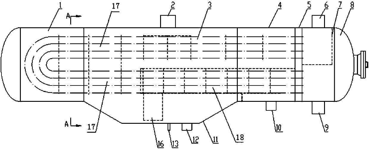
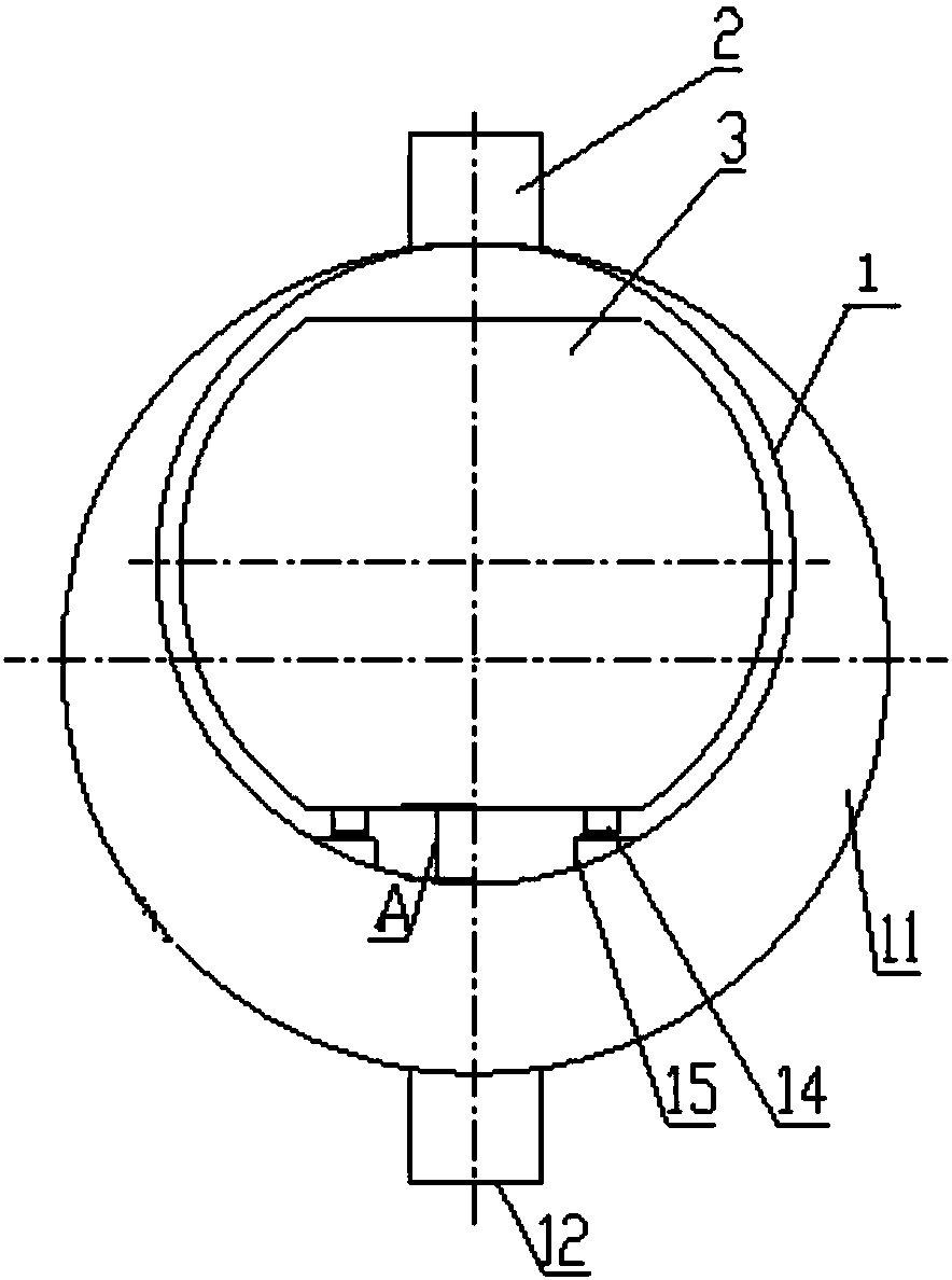
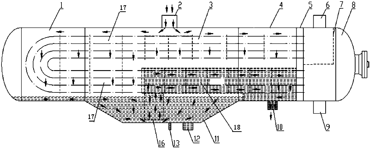
[0020] refer to Figure 1-3 As shown, the cylinder section 4 is welded to the tube sheet 5, the eccentric shell 11 (composed of two eccentric conical shells and a large-diameter cylinder), the cylinder section 4 and the cylinder body 1 form the shell, and the tube sheet 5 is connected to the U-shaped heat exchange tube bundle 3 , The U-shaped heat exchange tube bundle 3 is divided into a saturation section 17 and a cooling section 18 . The eccentric case 11 is eccentric downward relative to the barrel body 1 and the barrel section 4. The eccentric case 11 sinks below the bottom of the barrel body 1 and the barrel section 4 to form a drainage well. Drain well, the bottom of the drain well is provided with an emergency drain port 12 and a water discharge port 13, the upper part of the eccentric shell 11 is provided with a steam inlet 2, the cylinder section 4 is provided with an air release port of the cooling section and a drain outlet 10, and the upper part of the cylinder bod...

Embodiment 2

[0022] This embodiment is basically the same as Embodiment 1, the difference being that the emergency drain opening 12 is set at the bottom of the drain well, and the water outlet is at the lowest point of the emergency drain pipeline.


PUM


Abstract

The invention discloses a heating network heater internally provided with a draining well and belongs to the field of power station auxiliary devices. The heating network heater internally provided with the draining well comprises a shell. The shell comprises a cylinder body and a cylinder section connected with the cylinder body. A heat exchange pipe bundle is arranged in the shell. The heat exchange pipe bundle is divided into a saturation section and a drainage cooling section. The shell further comprises an eccentric shell connected with the cylinder body and the cylinder section. The eccentric shell is downward eccentric relative to the cylinder body and the cylinder section. The portion, below the bottoms of the cylinder body and the cylinder section, of the eccentric shell sinks toform the draining well. The control water level of the draining well is controlled to be located between the bottom of the heat exchange pipe bundle and the bottoms of the cylinder body and the cylinder section. The drainage cooling section of the heat exchange pipe bundle is of a siphonic structure. The inlet pipe of the drainage cooling section of the heat exchange pipe bundle goes deep into thebottom of the eccentric shell. The portion, located below the center line of the shell and outside the drainage cooling section, of the heat exchange pipe bundle is still used as the saturation section. The heating network heater internally provided with the draining well optimizes the stress condition of the draining well, lightens the shock of steam to the pipe bundle, simplifies water level control, avoids the situation that the drainage cooling section operates at a low water level or operates without water and improves the heat exchange efficiency, the equipment operates stably, the occupied space is small, and the material consumption of the equipment is small.

Description

technical field [0001] The invention belongs to the field of power station auxiliary machines. Background technique [0002] The heat network heaters of thermal power plants or other heating systems are generally equipped with drain wells compatible with drain pumps in order to ensure stable operation of the unit. The setting of the drainage well generally adopts a split type, that is, a separate drainage tank is installed at the lower part of the equipment. There is also a horizontal semicircular drainage well structure (referred to as bottom integrated drainage well) at the bottom of the heating network heater cylinder. [0003] There are deficiencies: the heat network heater using the split-type drainage well takes up a lot of space, consumes a lot of materials, the manufacturing cost is high, and the water level control is complicated. The heating network heater with integrated drainage well at the bottom has poor stress conditions for the end plate of the drainage wel...

Claims


Application Information

Patent Timeline
Patent Type & Authority Applications(China)
IPC IPC(8): F28D7/06F28F9/00F28F9/26F28F17/00
Inventor 樊进国邓科季敏东曾金辉
Owner DONGFANG BOILER GROUP OF DONGFANG ELECTRIC CORP
Why Eureka
Try Eureka