Test loading device for the fuel tank under the fuel EMU

A technology of loading device and EMU, applied in railway vehicle testing and other directions, can solve the problems of inaccurate test results, narrow space, uneven load, etc., and achieve the effect of reducing manual operation cost, accurate loading area and improving test efficiency.

Active Publication Date: 2015-12-30
CRRC QINGDAO SIFANG CO LTD
View PDF5 Cites 0 Cited by
  • Summary
  • Abstract
  • Description
  • Claims
  • Application Information

AI Technical Summary

Problems solved by technology

However, after the test car body was placed on the test platform, it was found that the space under the car body was narrow. If a conventional counterweight device is used to complete the simulation of the fuel tank area for loading, it has the following defects: (1) The height of the space under the car body is small. During the loading process, it is difficult for the loading personnel to place the counterweight to the fuel tank area under the vehicle in a limited space
(2) The weight of the fuel tank is 8000Kg. It takes 4-5 hours to complete the 8000Kg counterweight in the under-vehicle area by manually loading the counterweight. During the loading process, the weight is gradually increased, resulting in a long test vehicle body Uneven loads over time make it difficult to collect true stress data
In order to ensure the accuracy of test data collection, at least 3 times of loading are carried out during the test process. The test period is too long, the labor intensity is extremely high, and the space is small, which is likely to cause danger.
(3) Manual counterweight loading is used, the center of gravity of the counterweight does not match the center of the test area, the loading quality cannot be accurately guaranteed, and the data repeatability is poor, resulting in inaccurate test results
(4) A large number of stress collection points need to be arranged in the loading area. During the counterweight process, the strain gauges and data lines are easily damaged.

Method used


Image

  • Test loading device for the fuel tank under the fuel EMU
  • Test loading device for the fuel tank under the fuel EMU
  • Test loading device for the fuel tank under the fuel EMU

Examples


Embodiment Construction

[0025] The specific implementation manners of the present invention will be further described in detail below in conjunction with the accompanying drawings and embodiments. The following examples are used to illustrate the present invention, but are not intended to limit the scope of the present invention.

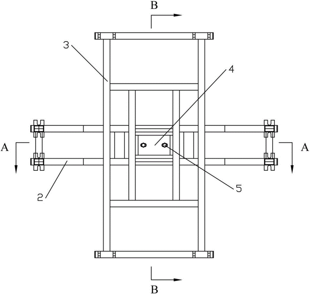
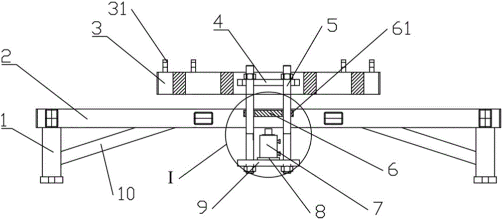
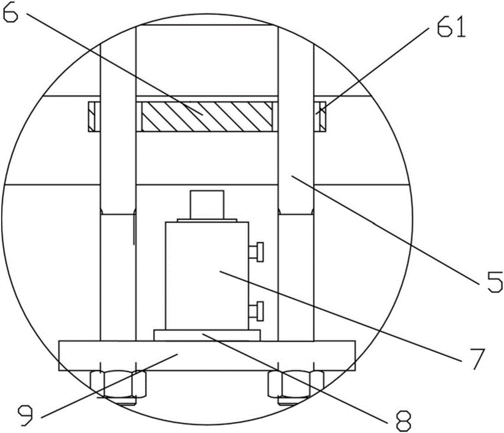
[0026] Such as Figures 1 to 4 As shown, the test loading device of the fuel tank under the fuel EMU of the present invention includes: a loading plate 9, a loading cylinder 7, a force sensor 8, a simulated fuel tank frame 3 and a reaction force frame, and the simulated fuel tank frame 3 is provided with four hooks 31. The simulated fuel tank frame 3 is fixedly installed on the fuel tank mounting seat of the vehicle body through the hook 31. The reaction force frame includes a frame body and a reaction force plate 6. The frame body is fixed on the test bench, and the reaction force plate 6 is set on the frame body; The frames 3 are connected; the loading cylinder 7 is pl...


PUM


Abstract

The invention relates to the technical field of train body strength tests and discloses a test loading device of a fuel motor train unit under-train fuel tank. The test loading device comprises a loading plate, a loading oil cylinder, a force sensor, a simulation fuel tank frame and a counterforce frame, the simulation fuel tank frame is fixedly mounted on a fuel tank mounting seat of a train body, the counterforce frame comprises a frame body and a counterforce plate, the frame body is fixed on a testbed, the counterforce plate is arranged on the frame body, the loading plate is arranged below the counterforce plate and connected with the simulation fuel tank frame through a connecting component, the loading oil cylinder is placed between the loading plate and the counterforce plate, and the force sensor is arranged between the loading oil cylinder and the loading plate. The test loading device is simple in structure, convenient to mount and demount, quick and accurate in loading, capable of repeatedly loading a suspension area of the under-train fuel tank in short time and guaranteeing a loading gravity position to be at the center of a loading area, high in loading accuracy and good in repeatability. A hydraulic loading mode is adopted, so that the test loading device is uniform in loading, capable of quickly adjusting and controlling loading range and free of sudden-change load.

Description

technical field [0001] The invention relates to the technical field of car body strength testing, in particular to a test loading device for a fuel tank under a fuel train multiple unit. Background technique [0002] When carrying out the static strength test of the head car body of the fuel EMU, it is necessary to carry out a 1:1 simulated loading on the area of ​​the fuel tank under the car to test whether the strength of the car body can safely support the fuel tank. However, after the test car body was placed on the test platform, it was found that the space under the car body was narrow. If a conventional counterweight device is used to complete the simulation of the fuel tank area for loading, it has the following defects: (1) The height of the space under the car body is small. During the process, it is difficult for the loading personnel to place the counterweight to the fuel tank area under the vehicle in a limited space. (2) The weight of the fuel tank is 8000Kg. ...

Claims


Application Information

Patent Timeline
Patent Type & Authority Patents(China)
IPC IPC(8): G01M17/08
Inventor 李明王伟华赵长龙刘为亚陈一萍张志强杨中林修霞
Owner CRRC QINGDAO SIFANG CO LTD
Why Eureka
Try Eureka