Site detection equipment for mechanical property of steel bars

A technology of on-site inspection and reinforcement mechanics, applied in the direction of applying stable tension/pressure to test the strength of materials, etc., can solve the problems of uncontrollability, waste of resources, length of reinforcement bars, etc., and achieve the effect of simple structure, convenient assembly, and quality assurance.

Inactive Publication Date: 2014-03-26
KUNSHAN CONSTRUCT ENG QUALITY TESTING CENT
View PDF8 Cites 15 Cited by
  • Summary
  • Abstract
  • Description
  • Claims
  • Application Information

AI Technical Summary

Problems solved by technology

However, the current displacement detection is realized by adding a displacement extensometer. This kind of equipment realizes the tensile performance test of the steel bar through the hydraulic system, and has the function of strictly controlling the loading speed. In the actual binding, some steel bars are arranged horizontally, some are vertically arranged, and some are even arranged obliquely, and the steel bars are long. Even if the equipment is moved to the site, the test cannot be carried out. Therefore, the mechanical performance testing of all related steel bars All require indoor inspection, which is meaningful for material type inspection or factory inspection, which requires the control of the testing equipment environment, but for engineering, the significance is not very obvious
In addition, due to the lack of a social integrity system, the current engineering material testing requirements in my country are witness sampling testing. It is difficult to guarantee the authenticity of whether the sample represents the mother parent. Many have done special processing, especially welding. The quality of the welded joints produced by the actual project (direct welding on site, see the photo) is uncontrollable. Strict regulations have been made. After each test, these test samples can only be sent to the steelmaking plant as waste products for re-smelting, resulting in a lot of waste of resources.

Method used


Image

  • Site detection equipment for mechanical property of steel bars
  • Site detection equipment for mechanical property of steel bars
  • Site detection equipment for mechanical property of steel bars

Examples


Embodiment

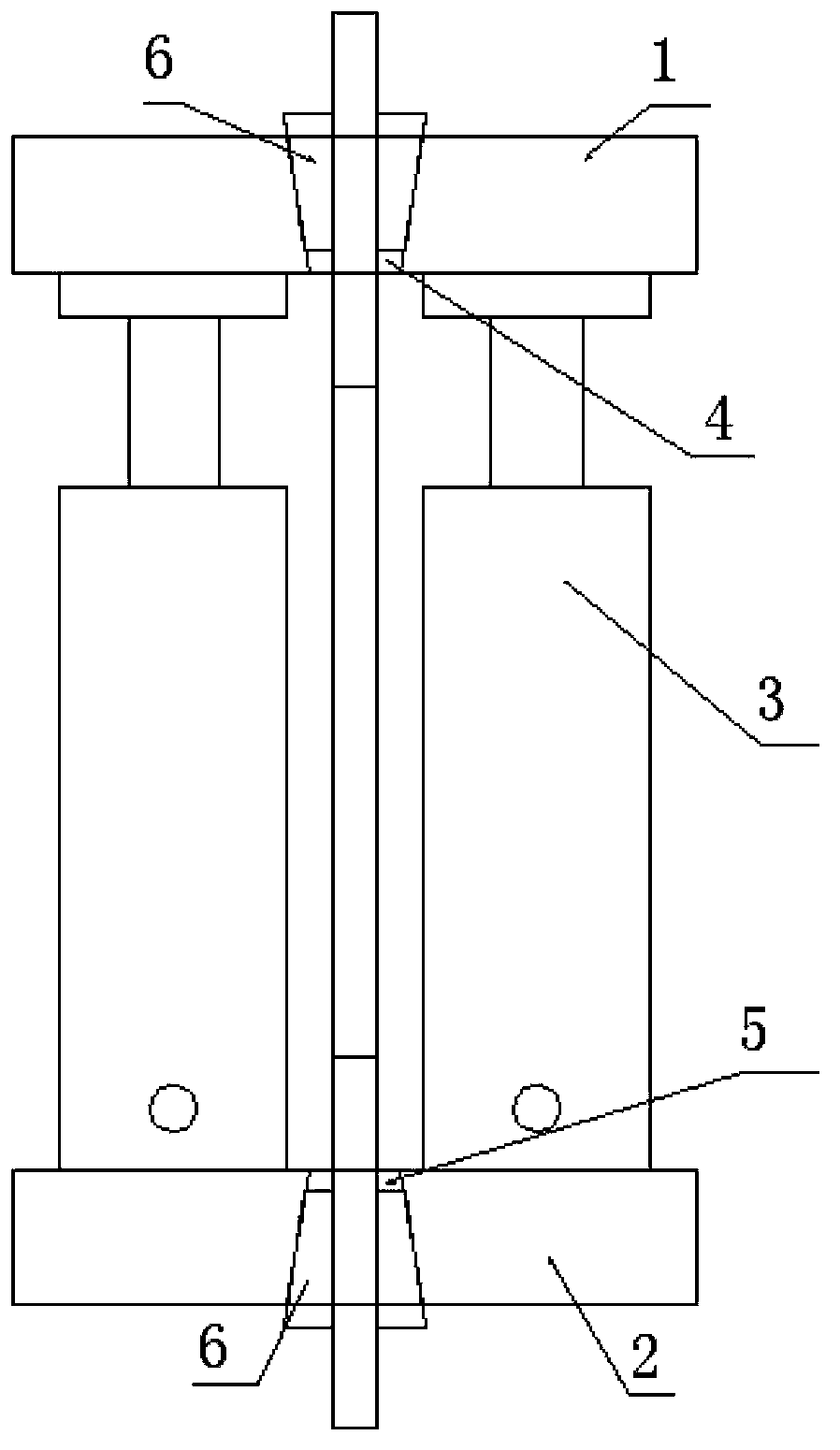
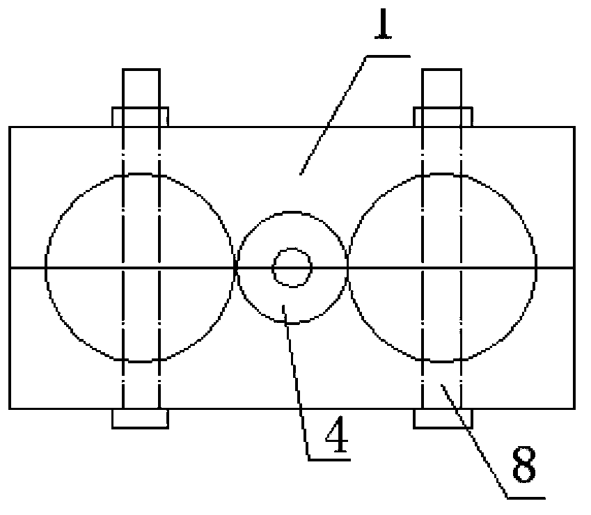
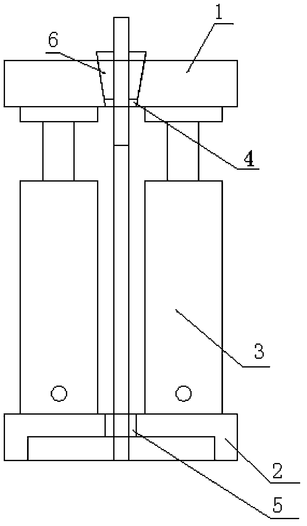
[0019] Embodiment: An on-site detection device for the mechanical properties of steel bars, including a fixture 1, a base 2 and a support device 3, the fixture 1 and the base 2 are respectively provided with coaxial first and second mounting holes 4, 5, and the first The interior of at least one of the first and second mounting holes 4 and 5 is provided with a steel bar fixing and clamping device 6, and the support device 3 can drive the clamp 1 to move relative to the base 2 along the axial direction of the first and second mounting holes 4 and 5. , first put the steel bars in the first and second installation holes 4, 5 of the fixture 1 and the base 2 and fix them through the steel bar fixing and clamping device 6 (for the steel bars in the anchored state, the second installation holes on the base 2 The steel bar fixing and clamping device 6 may not be used inside, the steel bar only needs to pass through the second installation hole on the base 2, and the steel bar fixing an...


PUM


Abstract

The invention discloses site detection equipment for mechanical properties of steel bars. The site detection equipment comprises a clamp, a base and a supporting device, wherein the clamp and the base are respectively provided with a first installing hole and a second installing hole which are coaxial; at least one of the first installing hole and the second installing hole is internally provided with a steel-bar fixing and clamping device; the supporting device can drive the clamp to move relatively to the base along the axial direction of the first installing hole and the second installing hole. The site detection equipment disclosed by the invention has the advantages that the structure is simple, the assembly is convenient, the steel bars in various states in engineering can be detected, the accuracy of the detection results of the steel bars can be ensured and the quality of engineering construction is guaranteed.

Description

technical field [0001] The invention relates to a testing device for the mechanical properties of steel bars, in particular to an on-site testing device for the mechanical properties of steel bars. Background technique [0002] For concrete structures, the mechanical properties of steel bars are the most important indicator of their load-bearing performance. Therefore, testing the mechanical properties of steel bars is an important means to ensure their quality. Structural engineering requires the re-inspection of the mechanical properties of steel bars, especially for joints that are welded or mechanically connected. However, the current displacement detection is realized by adding a displacement extensometer. This kind of equipment realizes the tensile performance test of the steel bar through the hydraulic system, and has the function of strictly controlling the loading speed. In the actual binding, some steel bars are arranged horizontally, some are vertically arranged,...

Claims


Application Information

Patent Timeline
Patent Type & Authority Applications(China)
IPC IPC(8): G01N3/08
Inventor 洪鑫王志龙陈可君王鹏飞龚朝龙
Owner KUNSHAN CONSTRUCT ENG QUALITY TESTING CENT
Why Eureka
Try Eureka