Gas and liquid two-phase flow loop corrosion experiment device

A gas-liquid two-phase flow and corrosion experiment technology, which is applied in the fields of weather resistance/light resistance/corrosion resistance, measuring devices, instruments, etc., can solve the problem of corrosion, affect the accuracy of corrosion research data and actual reference value, and produce liquid corrosion sex problems

Inactive Publication Date: 2014-03-26
RES INST OF SHAANXI YANCHANG PETROLEUM GRP
View PDF8 Cites 31 Cited by
  • Summary
  • Abstract
  • Description
  • Claims
  • Application Information

AI Technical Summary

Problems solved by technology

However, usually in the process of oil and gas mixed transportation, the gas phase medium of the reservoir often contains CO 2 、H 2 S and other gases or use CO in oil and gas development to enhance recovery 2 The CO carried out in the process of oil flooding technology 2 gas, which is severely corrosive after dissolving in the liquid phase; in addition, with the middle and late stages of oil recovery, CO 2 The content of water and water will gradually increase, which will also lead to the strengthening of the corrosiveness of the produced fluid
The corrosion law and mechanism of materials under simulated corrosion conditions are often different from those obtained from experiments at room temperature and pressure. In the past, when studying the corrosion behavior, characteristics and mechanism of gas-liquid two-phase flow or multi-phase flow, rotation The disc test device, the impingement jet test device, and the high-temperature and high-pressure reactor are used to complete the test, which is significantly different from the hydrodynamic properties of the gas-liquid two-phase flow in the actual oil and gas production process. The simulated working conditions are carried out, which affects the accuracy and practical reference value of the gas-liquid two-phase flow accelerated corrosion research data

Method used


Image

  • Gas and liquid two-phase flow loop corrosion experiment device
  • Gas and liquid two-phase flow loop corrosion experiment device
  • Gas and liquid two-phase flow loop corrosion experiment device

Examples


Embodiment Construction

[0021] The present invention will be further described below in conjunction with the drawings.

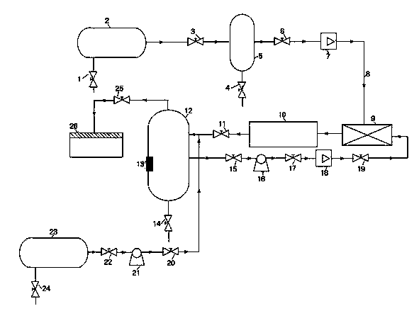
[0022] The invention provides a gas-liquid two-phase flow loop corrosion experiment device, with reference to figure 1 As shown, it includes a gas-phase flow pipeline, a liquid-phase flow pipeline, and a gas-liquid two-phase flow mixing pipeline; the gas-phase flow pipeline is sequentially connected with a gas storage tank 2, a control valve 3, a gas regulator tank 5, and a gas The regulating valve 6, the gas flow meter 7 and the gas-liquid mixer 9; the liquid-phase flow pipeline is connected to the liquid storage tank 12, the control valve three 15, the main liquid pump 16, the liquid regulating valve 17, and the liquid flow meter 18. The control valve 29 and the gas-liquid mixer 9; the gas-liquid two-phase flow mixing pipeline is connected with the gas-liquid mixer 9, the experimental test module 10, the control valve II 11 and the liquid storage tank 12 through the pipeline; install...


PUM


Abstract

The invention relates to the field of oil and gas field corrosion research, in particular to a gas and liquid two-phase flow loop corrosion experiment device, which is applicable to coupon corrosion experiment and in-situ corrosion electrochemical test of gas and liquid two-phase flow of an oil and gas field production system on an oil pipe under the simulated working condition. An experiment testing module is arranged in a horizontal pipeline, and oil and gas field high-temperature and high-pressure fluid simulated by an experiment device is subjected to loop corrosion experiment by using an electrochemical workstation and a three-electrode electrochemical corrosion measuring device, so that flow accelerated corrosion weight loss and appearance features are obtained; an 'in-situ' electrochemical signal of a working electrode in simulated high-temperature and high-pressure fluid is monitored, so that the corrosion behavior and mechanism of the gas and liquid two-phase flow loop are mastered.

Description

Technical field [0001] The invention belongs to the field of oil and gas field corrosion research, and particularly relates to a gas-liquid two-phase flow loop corrosion experiment device, which is suitable for the coupon corrosion experiment and in-situ corrosion of oil pipes under simulated working conditions of gas-liquid two-phase flow in oil and gas field production systems Electrochemical testing. Background technique [0002] In the industrial production of oil and gas fields, the output from oil wells is mostly a gas-liquid two-phase or even multi-phase mixture, which is collected and transported to oil gathering stations or joint processing stations through surface pipelines. Gas-liquid two-phase mixed transportation technology can be seen everywhere in oil and gas production. It has the advantages of simplifying the process, reducing infrastructure investment, and increasing oil and gas production. It is the most challenging and promising technology in the field of oil ...

Claims


Application Information

Patent Timeline
Patent Type & Authority Applications(China)
IPC IPC(8): G01N17/00G01N17/02
Inventor 刘立尹志福朱世东张永强王珂李建东刘杰司小明魏彦林方晓君吕雷
Owner RES INST OF SHAANXI YANCHANG PETROLEUM GRP
Why Eureka
Try Eureka