Microwave device impedance measurement calibration method

A technology of microwave devices and calibration methods, applied in measuring devices, measuring electrical variables, measuring resistance/reactance/impedance, etc., can solve the problems of limited measurement bandwidth of TRL algorithm, reduce design and processing requirements, expand working frequency band, simplify personal number effect

Inactive Publication Date: 2014-03-26
NAT UNIV OF DEFENSE TECH
View PDF4 Cites 40 Cited by
  • Summary
  • Abstract
  • Description
  • Claims
  • Application Information

AI Technical Summary

Problems solved by technology
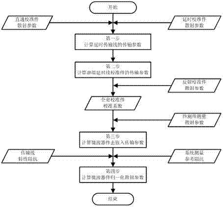
[0005] The technical problem to be solved by the present invention is to provide an improved TRL calibration method for the limited measurement bandwidth of the TRL algorithm, which is based on the existing measurement data and uses virtual measurement technology to solve the local phase ambiguity problem, which can reduce the delay calibration number of pieces, simplified TRL measurement steps and expanded TRL algorithm calibration measurement bandwidth

Method used


Image

  • Microwave device impedance measurement calibration method
  • Microwave device impedance measurement calibration method
  • Microwave device impedance measurement calibration method

Examples


Embodiment 1

[0020]

[0021] Scattering parameters of time-lapse calibration kit

[0022]

[0023] Respectively converted into transmission parameters can be obtained:

[0024] Thru Calibration Transfer Parameters

[0025]

[0026] Transmission Parameters for Time Delay Calibration Kit

[0027]

[0028] make ,in for the inverse matrix of .

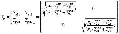
[0029] Then the transmission parameters of the delayed transmission line can be expressed as

[0030]

[0031] In the formula respectively for the equation of two, and satisfy .

[0032] In the second step, the transmission parameters of the virtual delay line calibration piece are calculated. Write down the delay transmission line length contained in the original delay calibration piece as , the length of the newly added delay transmission line of the virtual delay calibration part is , then the newly added length is The transmission parameters of the virtual delay transmission line are

[0033]

[0034] Furth...

Embodiment 2

[0044]

[0045] Scattering parameters of time-lapse calibration kit

[0046]

[0047] Respectively converted into transmission parameters can be obtained:

[0048] Thru Calibration Transfer Parameters

[0049]

[0050] Transmission Parameters for Time Delay Calibration Kit

[0051]

[0052] make

[0053] Then the transmission parameter of the delayed transmission line is

[0054]

[0055] In the formula respectively for the equation of two, and satisfy .

[0056] The second step, the third step and the fourth step are the same as in the first embodiment.


PUM


Abstract

The invention introduces a microwave device impedance measurement calibration method. The method comprises the following steps: (1), calculating time-delay transmission line transmission parameters through real-time measured data of straight-through calibration member scattering parameters and time-delay calibration member scattering parameters; (2), embedding a newly added virtual transmission line in an original time-delay calibration member, and calculating the transmission parameters of a virtual time-delay calibration member; (3), according to a conventional TRL calibration method, extracting calibration coefficients of a measuring clamp, and performing matrix inversion and multiplication operation to obtain a microwave device de-embedding transmission parameters; and (4), performing impedance normalization transformation on the microwave device de-embedding transmission parameters to obtain normalized microwave device normalization scattering parameters relative to system measurement reference impedance. The method makes up the measurement errors caused by inconsistence of transmission line characteristic impedance and the system measurement reference impedance, and realizes microwave device impedance measurement with an ultra wide band and high precision. At the same time, the improved microwave device impedance measurement calibration method can substantially reduce design processing requirements of a calibration device, thereby having high versatility.

Description

technical field [0001] The invention relates to an impedance measurement and calibration method, in particular to a microwave device impedance measurement and calibration method with de-embedding function. Background technique [0002] Microwave devices such as field effect transistors, transistors, detector tubes, chip capacitors, chip inductors, etc. are often used in microwave circuit design. Because the operating frequency is too high, the device package will introduce parasitic effects, so it is necessary to accurately measure the impedance characteristics of the device . [0003] The impedance characteristics of microwave devices are generally described by scattering parameters (S parameters). The measuring instrument usually chooses a vector network analyzer, but a vector network analyzer can only measure microwave devices that can match its ports, such as coaxial ports and waveguide ports. There are many types of microwave device interfaces, and it is necessary to u...

Claims


Application Information

Patent Timeline
Patent Type & Authority Applications(China)
IPC IPC(8): G01R27/02G01R35/00
Inventor 杨成易波王为刘培国刘继斌周东明李高升
Owner NAT UNIV OF DEFENSE TECH
Why Eureka
Try Eureka