Lightning shielding and counterattack identification method for overhead transmission lines
An overhead transmission line and identification method technology, which is applied in the identification field of lightning shielding and counterattack on transmission lines, can solve the problems of no method for distinguishing, characteristic signal interference annihilation, and criterion failure, etc., to achieve clear and intuitive physical concepts, calculation Simple, easy-to-achieve effects
- Summary
- Abstract
- Description
- Claims
- Application Information
AI Technical Summary
Problems solved by technology
Method used
Image
Examples
Embodiment 1
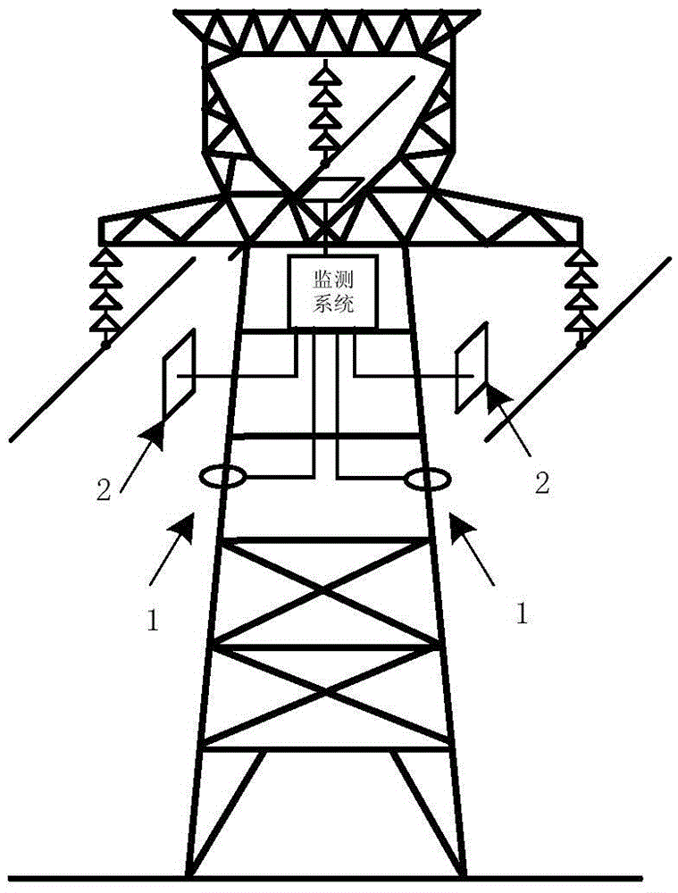
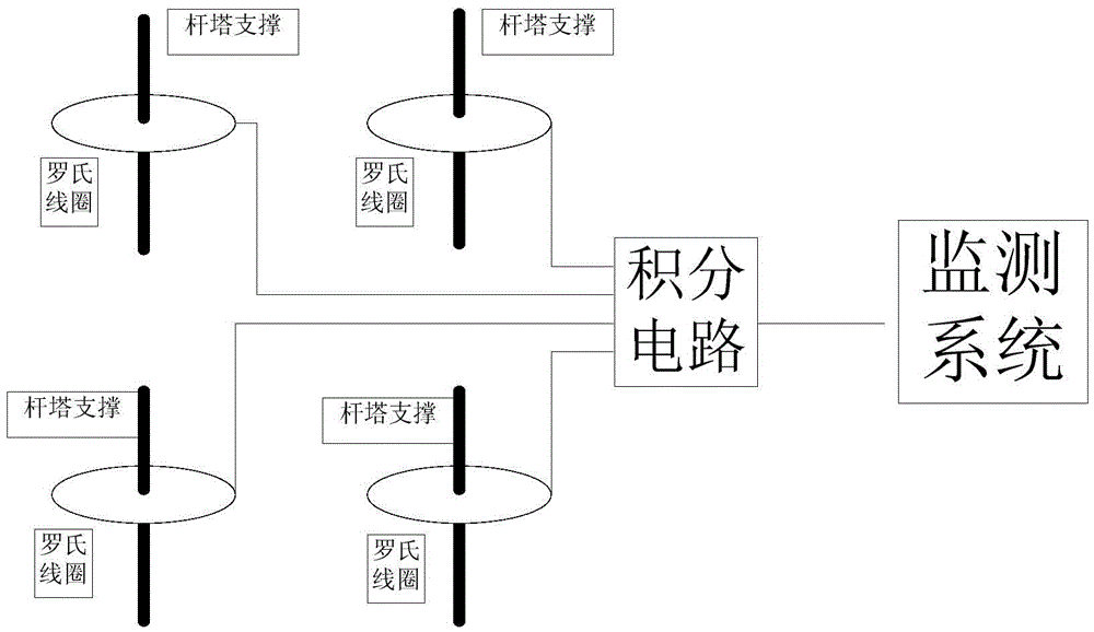
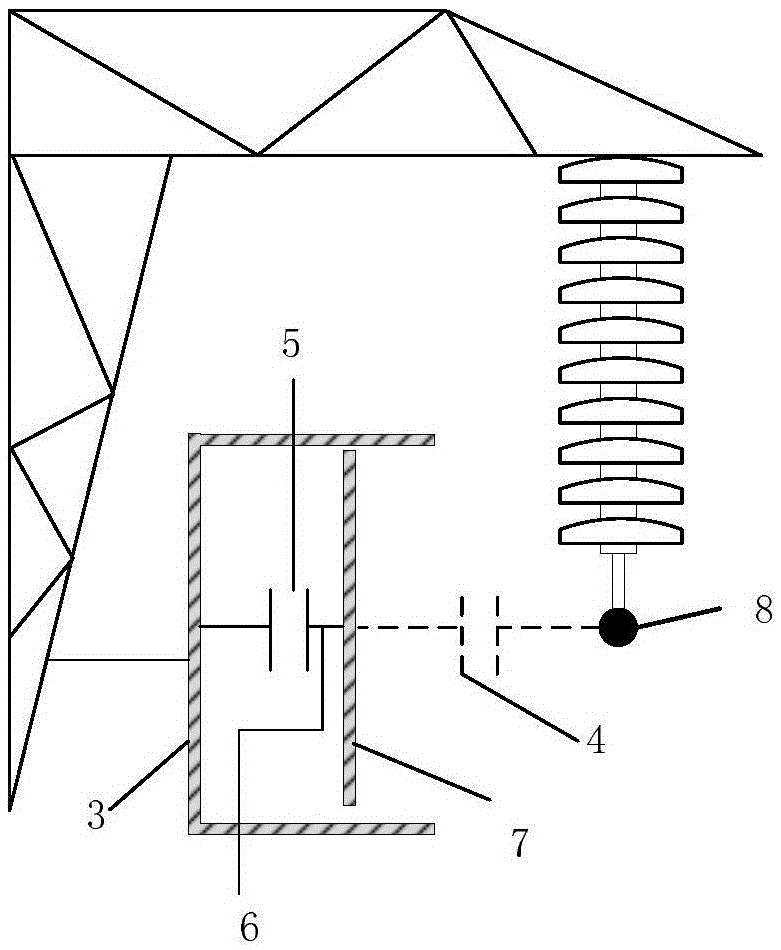
[0044] figure 1 Schematic diagram of the lightning monitoring system, figure 2 It is the schematic diagram of the tower-to-earth current measurement system, image 3 The schematic diagram of the non-contact overvoltage sensor, Figure 4 is a 110kV transmission line model, Figure 5 is the tower structure and multi-wave impedance model, where, Figure 5 a is the tower structure, Figure 5 b is the multiwave impedance model, Figure 6 It is a schematic diagram of the non-flashover of the basic tower top insulators struck by lightning, in which, Figure 6 a is the voltage waveform across the insulator, Figure 6 b is the tower current waveform into the ground.
[0045] The present invention introduces the potential difference at both ends of the insulator string and the ground current of the tower as the characteristic signal input quantity, and the required signal passes through figure 1 The lightning monitoring system shown is obtained. Such as figure 2 As shown, a ...
Embodiment 2
[0069] The difference between this embodiment and embodiment 1 is only:
[0070] The identification method provided by the embodiment of the present invention specifies the reference direction: the potential difference Uins of the insulator string is positive from the wire side to the tower side, and the ground current Ig of the tower is positive from the ground to the tower. Transmission line lightning strike simulation model such as Figure 4 As shown, the tower structure and its multi-wave impedance model are as follows Figure 5 as shown, Figure 5 is the tower structure and multi-wave impedance model, where, Figure 5 a is the tower structure, Figure 5 b is the multi-wave impedance model, and the lightning current adopts 2.6 / 50us waveform. The tower on which the signal acquisition device is installed is called the basic tower.
[0071] When the negative polarity lightning strikes the top of the tower or the lightning protection line close to the top of the tower (he...
Embodiment 3
[0088] The difference between this embodiment and embodiment 2 only lies in:
[0089] When a lightning strike occurs on the transmission line, the above method can be used to realize the correct identification of lightning shielding and counterattack. The specific implementation flow chart is as follows Figure 6 shown.
[0090] Specific steps are as follows:
[0091] 1) Normalize the signal. Calculate the D value, if D=+1, the lightning strike point is located on the top of the tower (the lightning protection line is close to the top of the tower), if D=-1, the lightning strike point is located on the wire;
[0092] 2) Calculate U5us, if U5us<Uthres, the basic tower will flashover due to lightning strike. If D=+1 in step 1), it is the counter-attack flashover of the basic tower; if D=-1 in step 1), it is the flashover of the basic tower;
[0093] 3) Calculate U1.5ms, if U1.5ms
PUM
 Abstract
Description
Claims
Application Information
 - R&D
- Intellectual Property
- Life Sciences
- Materials
- Tech Scout
- Unparalleled Data Quality
- Higher Quality Content
- 60% Fewer Hallucinations
Browse by: Latest US Patents, China's latest patents, Technical Efficacy Thesaurus, Application Domain, Technology Topic, Popular Technical Reports.
© 2025 PatSnap. All rights reserved.Legal|Privacy policy|Modern Slavery Act Transparency Statement|Sitemap|About US| Contact US: help@patsnap.com


