
Battery manufacturing equipment, battery no-cavity vacuum liquid-drawing device and battery vacuum-pumping packaging method

A technology of vacuuming and vacuuming tubes, which is applied in the field of battery manufacturing equipment and its cavity-free vacuum pumping device, which can solve the problems of long vacuuming time, complex mechanism structure, frequent cleaning and maintenance, etc., to simplify the equipment structure and avoid cleaning work , The effect of reducing equipment production costs

Active Publication Date: 2014-03-26
DONGGUAN HONBRO LI BATTERY EQUIP TECH
View PDF4 Cites 24 Cited by
  • Summary
  • Abstract
  • Description
  • Claims
  • Application Information

AI Technical Summary

Problems solved by technology

[0003] However, although the above-mentioned existing battery vacuum structure can realize the basic vacuum packaging process in the battery production process, it is found that its own structure and performance cannot achieve the best use effect and work efficiency in actual use, and still There are many deficiencies, and the deficiencies are summarized as follows: On the one hand, the entire mechanism structure of the aforementioned large sealed cavity structure is complex and the cost is high; on the other hand, the cavity size is large, and the entire lithium battery needs to be sealed in its cavity In the body, the vacuuming time is long, the energy consumption is large, and the production efficiency is low; moreover, since its head, bayonet, pressing plate, battery positioning plate and other components are located in the large sealed cavity, after the air bag is punctured When the electrolyte is pumped by vacuum, the electrolyte will be pumped out in a spray state, and the sprayed electrolyte will pollute the cavity and its internal parts such as the head, bayonet, pressure plate, battery positioning plate, etc., so that the cavity needs to be cleaned regularly. The surface of the package is polluted and needs to be ground, cleaning and maintenance are frequent and difficult, and the maintenance cost is high

Method used


Image

  • Battery manufacturing equipment, battery no-cavity vacuum liquid-drawing device and battery vacuum-pumping packaging method
  • Battery manufacturing equipment, battery no-cavity vacuum liquid-drawing device and battery vacuum-pumping packaging method
  • Battery manufacturing equipment, battery no-cavity vacuum liquid-drawing device and battery vacuum-pumping packaging method

Examples


Embodiment Construction

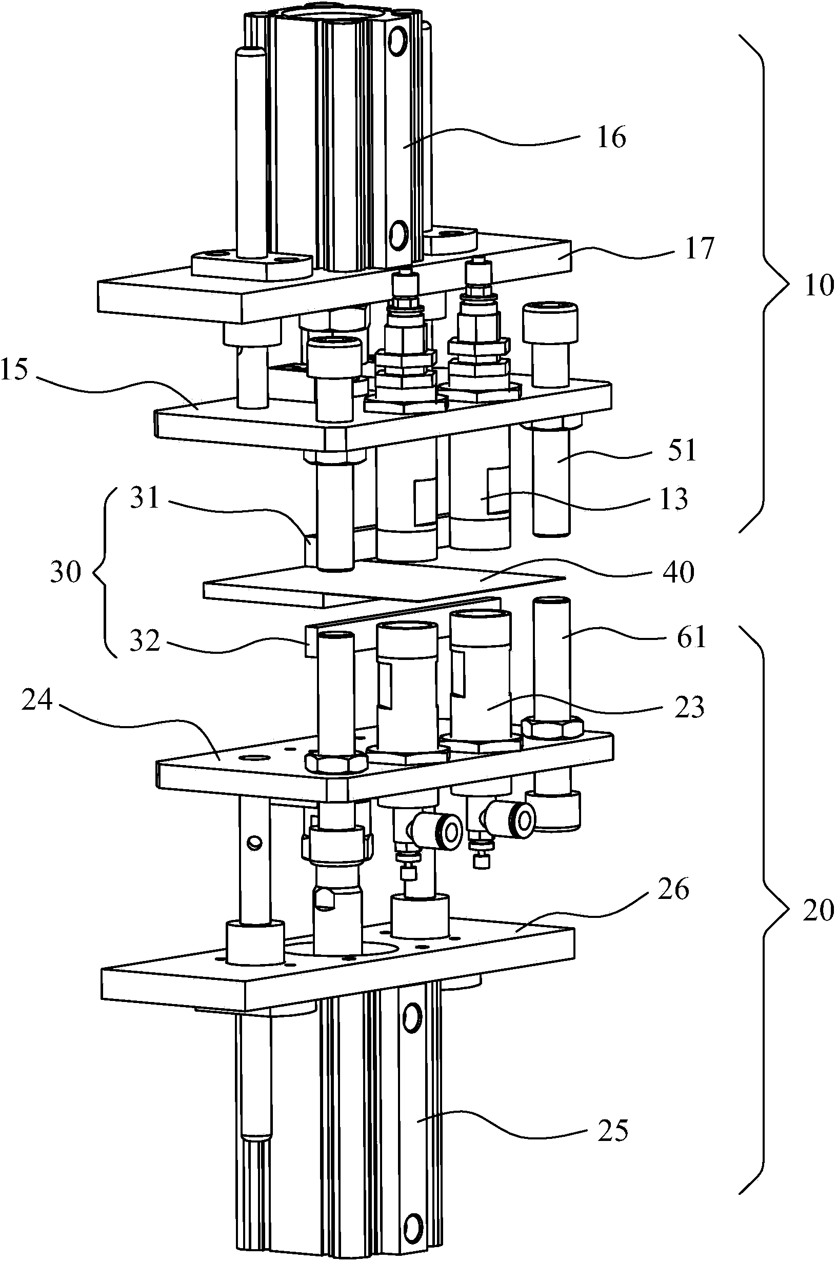
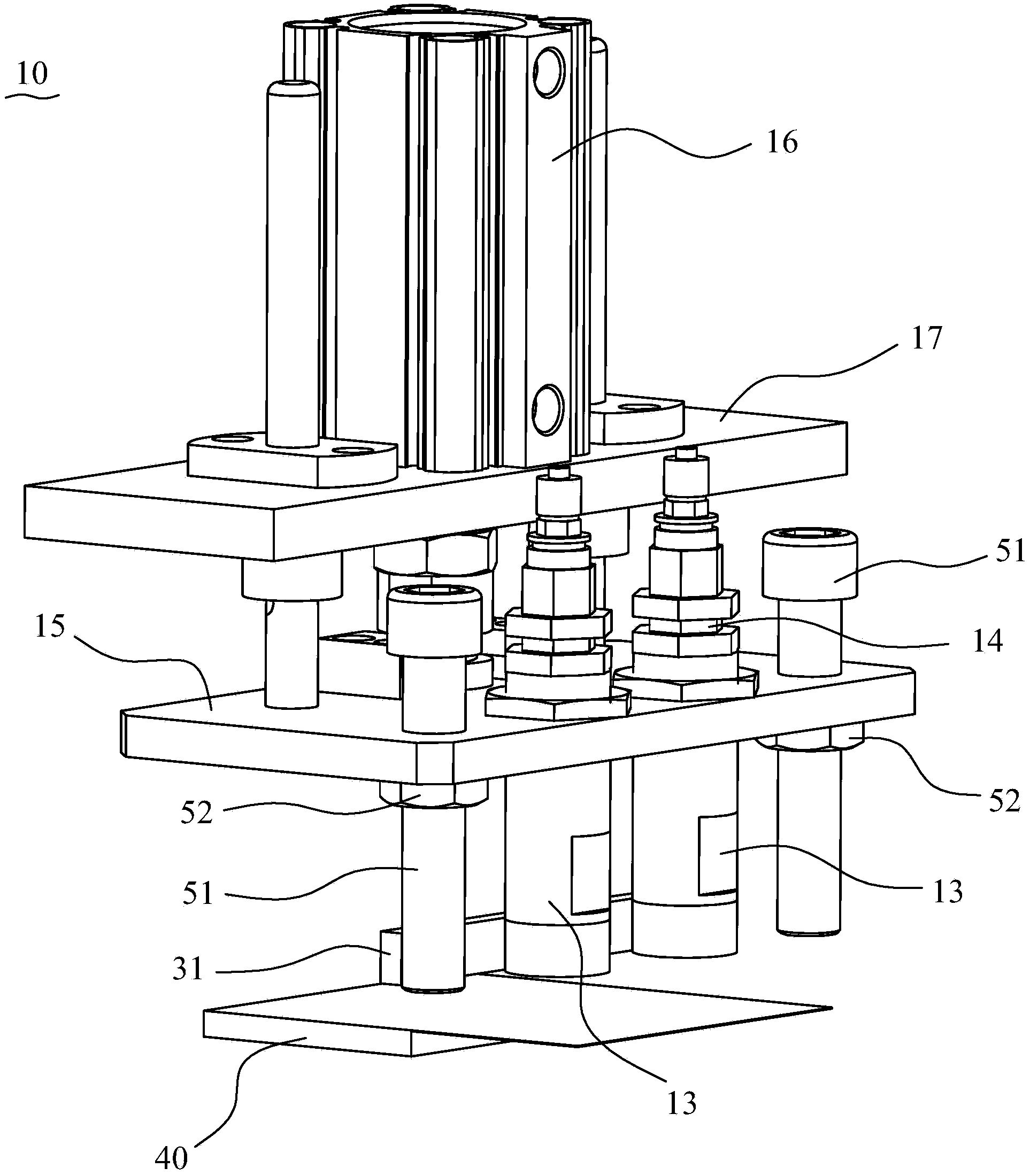
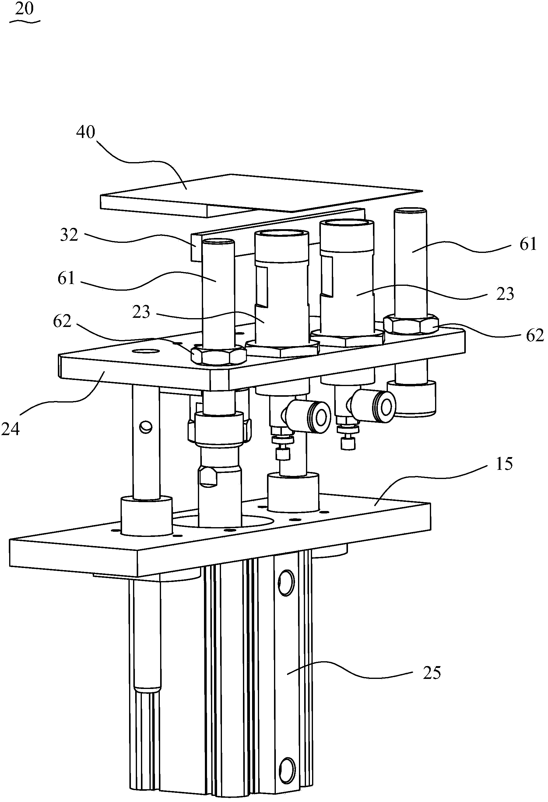
[0036] Please refer to Figure 1 to Figure 8 As shown, it shows the specific structure of a preferred embodiment of the present invention, a battery chamberless vacuum pumping device for battery manufacturing equipment. This embodiment takes lithium battery packaging as an example for illustration, including The seal piercing mechanism 10 and the sealing vacuum mechanism 20 arranged opposite to each other, and the sealing mechanism 30 located outside the seal piercing mechanism 10 and the sealing vacuum mechanism 20 .

[0037] Wherein, the seal piercing mechanism 10 includes an upper suction cup 11 , a movable bayonet 12 , a bayonet guide sleeve 13 , a bayonet driving element 14 , an upper movable seat plate 15 and an upper seat plate driving element 16 . The above-mentioned upper seat board driving element 16 is installed on the fixed plate 17 of a frame, and the fixed plate 17 is provided with two guide shafts, and the aforementioned upper movable seat plate 15 is sleeved on...


PUM


Abstract

The invention discloses battery manufacturing equipment, a battery no-cavity vacuum liquid-pumping device and a battery vacuum-pumping packaging method; the battery no-cavity vacuum liquid-pumping device includes a seal piercing mechanism and a seal vacuum pumping mechanism which are arranged opposite to each other, and also includes a sealing mechanism which is located near the outer side of the seal piercing mechanism and the seal vacuum pumping mechanism; the seal piercing mechanism comprises an upper sucking disc and a movable bayonet, and when in piercing, the movable bayonet penetrates the upper sucking disc to pierce a battery package body; the seal vacuum pumping mechanism comprises a lower sucking disc and a vacuum pumping tube, the lower sucking disc is provided with a vacuum suction port communicated with the vacuum pumping tube, and the orientations of openings of the upper sucking disc and the lower sucking disc are opposite to each other; and during vacuum pumping of a battery, the upper sucking disc and the lower sucking disc are respectively sealed and absorbed on local positions of two side surfaces of the battery package body. An upper sucking disc and the lower sucking disc type piercing and vacuum-pumping structure is adopted, the equipment structure is simplified, the production efficiency is improved, the production energy consumption is reduced, frequent cleaning work is avoided, and the repair and maintenance are more convenient.

Description

technical field [0001] The invention relates to the technology in the field of battery manufacturing equipment, in particular to a battery manufacturing equipment and a cavityless vacuum pumping device and a vacuum packaging method thereof. Background technique [0002] At present, in the battery production industry, in the battery production process, after the electrolyte is injected and left to stand, it is necessary to extract the excess electrolyte that has not been absorbed by the battery cell and the gas generated during the production process, and then put the aluminum plastic in a vacuum environment. The film is sealed under heat and pressure. In order to complete this process, the upper chamber, the lower chamber, and the load-bearing fixture are closed in the industry to form a large sealed chamber. Inside the chamber, there are upper and lower heads for packaging, a bayonet for piercing the aluminum-plastic film, and compressed air. The upper and lower pressure p...

Claims


Application Information

Patent Timeline
IPC IPC(8): H01M2/36H01M50/691
CPCH01M10/0404H01M50/691Y02E60/10
Inventor 喻世民费维刘高亮张强廖均克
Owner DONGGUAN HONBRO LI BATTERY EQUIP TECH
Features
  • Generate Ideas
  • Intellectual Property
  • Life Sciences
  • Materials
  • Tech Scout
  • Unparalleled Data Quality
  • Higher Quality Content
  • 60% Fewer Hallucinations
Learn More