Supercharge Your Innovation With Domain-Expert AI Agents!

Small-sized ferrite chip antenna

A ferrite sheet, ferrite technology, applied in the direction of the loop antenna with a ferromagnetic material core, etc., can solve the problem of strength decline and achieve the effect of avoiding attenuation

Inactive Publication Date: 2014-03-26
SHENZHEN MICROGATE TECH
View PDF4 Cites 0 Cited by
  • Summary
  • Abstract
  • Description
  • Claims
  • Application Information

AI Technical Summary

Problems solved by technology

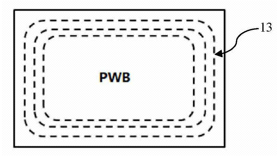
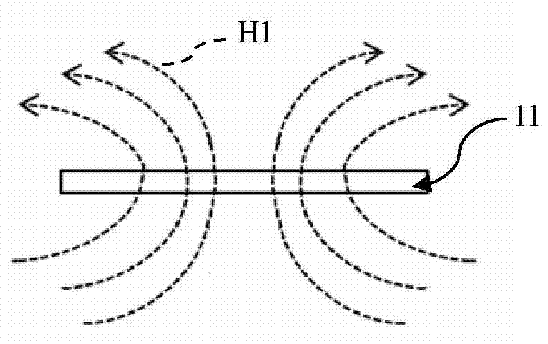
Please see attached Figure 1 to Figure 3 , Figure 1 to Figure 3 It is a schematic diagram showing the form of communication of a card 11 equipped with a PWB (English Printed wire board, the official translation is a printed circuit board) antenna 13 in the card slot 12. image 3 In the example shown above, in the electromagnetic waves emitted by the PWB antenna 13 in the card 11, most of the magnetic field H is perpendicular to the metal card slot 12, and its strength will be greatly reduced due to attenuation such as metal reflection and absorption.

Method used


Image

  • Small-sized ferrite chip antenna
  • Small-sized ferrite chip antenna
  • Small-sized ferrite chip antenna

Examples


Embodiment 1

[0023] Embodiment 1: Please refer to the attached Figure 5 , firstly, according to different design requirements, use ferrite powder with different magnetic permeability, add binder, plasticizer, dispersant, etc., and prepare casting slurry by ball milling various base materials in a ball mill , In this embodiment, the magnetic permeability is preferably 70~200. Then, the LTCC wet process is used for lamination. In this embodiment, as Figure 5 The shown antenna is formed by stacking 5 layers of ferrite diaphragms 27; the specific steps are as follows: 1. Paste a layer of MIRA paper on the drool carrier board, and use screen printing technology to print metal patterns on the MIRA paper. Bottom surface electrodes 21 are formed. In the present embodiment, the antenna is in the shape of a cuboid as a whole, and there are 10 bottom surface electrodes 21 (the number of electrodes is not necessarily 10, and it is generally arranged symmetrically in an even number. How much the num...

Embodiment 2

[0026] Embodiment two: Please refer to the attached Figure 6 , the coil in this embodiment uses the same ferrite diaphragm 27 as in Embodiment 1, and the upper and lower substrates are changed to ferrite films 28 made of low permeability ferrite paste (u=4) , Low magnetic permeability materials have the advantages of good insulation performance and good magnetic permeability.

Embodiment 3

[0027] Embodiment three: Please refer to the attached Figure 7 In this embodiment, the same ferrite diaphragm 27 as in Embodiment 1 is used inside the coil, and the upper and lower substrates are replaced with ceramic films 29 made of ceramic slurry. The co-firing of ceramics and ferrite effectively solves the shortcoming of relatively brittle ferrite.


PUM


Abstract

The invention discloses a small-sized ferrite chip antenna. The small-sized ferrite chip antenna comprises: a base ferrite diaphragm, upper slash segments, lower slash segments and metal connecting bars, wherein one or more upper slash segments are obliquely arranged above the base ferrite diaphragm and one or more lower slash segments are obliquely arranged below the base ferrite diaphragm. The upper slash segments are connected with the lower slash segments with the metal connecting bars positioned in the base ferrite diaphragm so as to form a spiral coil wound around a horizontal axis. An upper surface diaphragm is arranged above the upper slash segment, a lower surface diaphragm is arranged below the lower slash segment, a surface electrode is arranged above the upper surface diaphragm and a bottom electrode is arranged below the lower surface diaphragm. The surface electrode and the bottom electrode are connected with each end of the spiral coil by the metal connecting bars. According to this arrangement, the antenna is wound around the horizontal axis, so that the magnetic field of the antenna is parallel to grooves and the attenuation caused by being orthogonal to the grooves can be avoided.

Description

technical field [0001] The invention discloses an antenna, in particular to a small ferrite chip antenna suitable for cards, labels and hand-held reader-writers. Background technique [0002] In recent years, there have been more and more applications of radio frequency identification technology (RFID) and near field communication technology (NFC). In order to communicate between mobile electronic devices such as mobile phones or between mobile electronic devices and readers, a common solution in the prior art is to equip mobile electronic devices with identifiable cards with communication antennas. Usually, The identifiable card is installed in the metal card slot of the mobile electronic device. Please see attached Figure 1 to Figure 3 , Figure 1 to Figure 3 It is a schematic diagram showing the form of communication of a card 11 equipped with a PWB (English Printed wire board, the official translation is a printed circuit board) antenna 13 in the card slot 12. ...

Claims


Application Information

Patent Timeline
IPC IPC(8): H01Q7/06
Inventor 赖定权梁启新付迎华陈鑫朱圆圆马龙陈基源齐治张海恩张美蓉
Owner SHENZHEN MICROGATE TECH
Features
  • R&D
  • Intellectual Property
  • Life Sciences
  • Materials
  • Tech Scout
  • Unparalleled Data Quality
  • Higher Quality Content
  • 60% Fewer Hallucinations
Learn More