Stripping machine

A technology of peeling machine and peeling roller, which is applied in the direction of dismantling/armouring cable equipment, etc., which can solve the problems of easy cuts to hands, waste wires, labor, and low efficiency, and achieve the effect of thorough stripping and simple structure

Inactive Publication Date: 2014-03-26
WUHU SHUNCHENG ELECTRONICS
View PDF5 Cites 10 Cited by
  • Summary
  • Abstract
  • Description
  • Claims
  • Application Information

AI Technical Summary

Problems solved by technology

[0003] The technical problem to be solved in the present invention is that the existing

Method used


Image

  • Stripping machine
  • Stripping machine
  • Stripping machine

Examples


Embodiment Construction

[0011] The preferred technical solution of the present invention will be described in detail below with reference to the accompanying drawings.

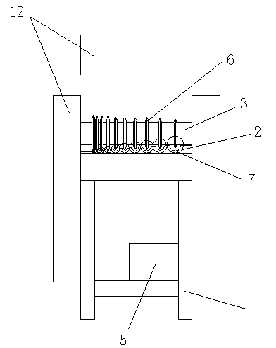
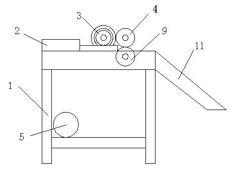
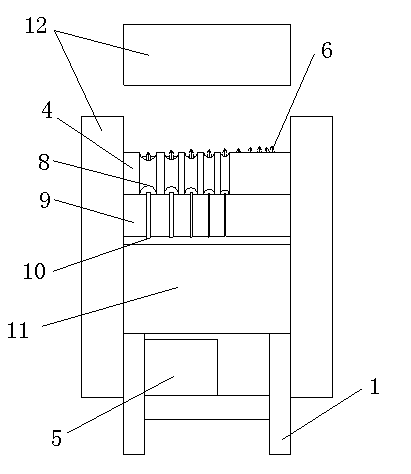
[0012] As shown in the figure, the peeling machine of the present invention includes a frame 1, a feeding guide tube 2, a peeling roller shaft 3, a rolling roller shaft 4, and a motor 5. The motor 5 is fixed under the frame 1, and the peeling roller shaft 3 and the rolling roller shaft 4 are driven by a motor 5. Both ends of the peeling roller shaft 3 and the rolling roller shaft 4 are fixed on the support 1, and the feeding guide tube 2 is fixed on the upper front side of the support 1. , And arranged from large to small, the peeling roller 3 is arranged behind the feeding guide tube 2, and a circle of blades 6 is provided on the peeling roller 3 at a position corresponding to the center of each feeding guide tube 2. The bracket 1 below the blade 6 is provided with a guide groove 7 corresponding to the size of the guide groove 7 and th...


PUM


Abstract

The invention discloses a stripping machine. The stripping machine includes a bracket, feeding guide pipes, a stripping roll shaft, a rolling compaction roll shaft and a motor, wherein the motor is fixed below the bracket, the stripping roll shaft and the rolling compaction roll shaft are both driven by the motor, the two ends of the stripping roll shaft and the two ends of the rolling compaction roll shaft are all fixed on the bracket, the feeding guide pipes are fixed on the upper front side of the bracket and arranged in a diameter decreasing manner, the stripping roll shaft is arranged behind the feeding guide pipes, and the rolling compaction roll shaft is arranged behind the stripping roll shaft. The stripping machine provided by the invention is applicable for the recovery of various waste wires longer than 30cm and with different diameters. The stripping machine has a simple structure, is applicable for different wire diameters, and achieves complete stripping, thereby avoiding a great number of shortcomings of manual stripping.

Description

Technical field [0001] The invention relates to a peeling machine for wire and cable recycling. Background technique [0002] Discarded wires and cables are generally recycled, while the outer skin and copper core are generally recycled separately, usually using manual knife cutting to avoid waste, but the labor efficiency is low and it is easy to cut hands. Summary of the invention [0003] The technical problem to be solved by the present invention is that the existing waste electric wires are recycled manually, which is low in efficiency and easy to cut hands. [0004] In order to solve the above technical problems, the present invention provides a peeling machine, including a bracket, a feeding guide tube, a peeling roller, a rolling roller, and a motor. The motor is fixed under the bracket, and the peeling roller and the rolling The roller shafts are driven by motors. Both ends of the peeling roller shaft and the crushing roller shaft are fixed on the bracket. The feeding guid...

Claims


Application Information

Patent Timeline
IPC IPC(8): H02G1/12
Inventor 杨自强田春连曹彩云
Owner WUHU SHUNCHENG ELECTRONICS
Why Eureka
Try Eureka