Rotor silicon steel sheet structure

A silicon steel sheet and rotor technology, applied in the field of rotor silicon steel sheet structure, can solve the problems of large waste of magnetic energy and low motor efficiency, and achieve the effects of high magnetic energy utilization rate, improved efficiency, and improved magnetic energy utilization rate

Inactive Publication Date: 2014-03-26
ANHUI JIANGHUAI AUTOMOBILE GRP CORP LTD
View PDF5 Cites 6 Cited by
  • Summary
  • Abstract
  • Description
  • Claims
  • Application Information

AI Technical Summary

Problems solved by technology

It can be seen that the more loops of magnetic lines of force formed inside the roto

Method used


Image

  • Rotor silicon steel sheet structure
  • Rotor silicon steel sheet structure
  • Rotor silicon steel sheet structure

Examples


Embodiment Construction

[0026] Embodiments of the present invention are described in detail below, examples of which are shown in the drawings, wherein the same or similar reference numerals designate the same or similar elements or elements having the same or similar functions throughout. The embodiments described below by referring to the figures are exemplary only for explaining the present invention and should not be construed as limiting the present invention.

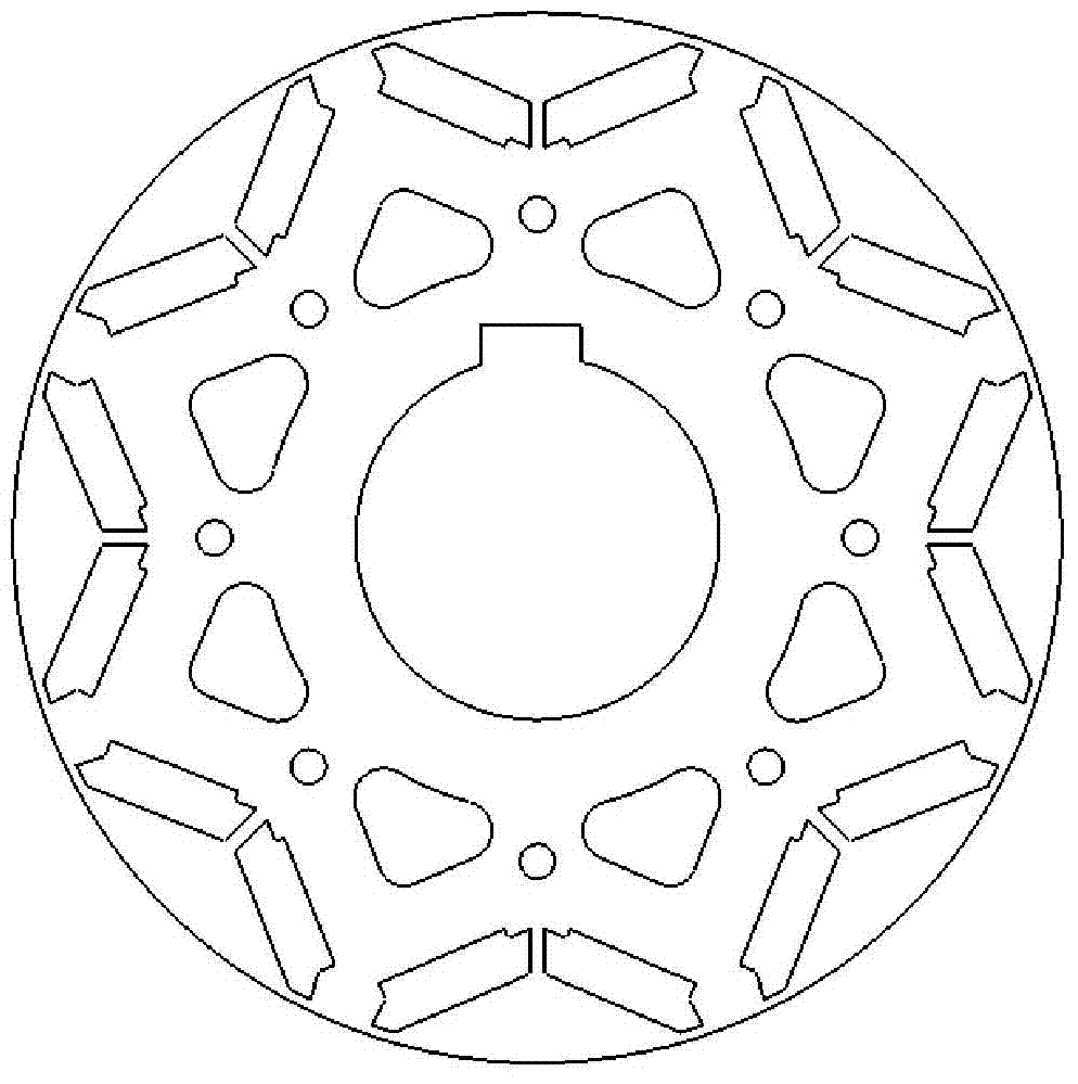
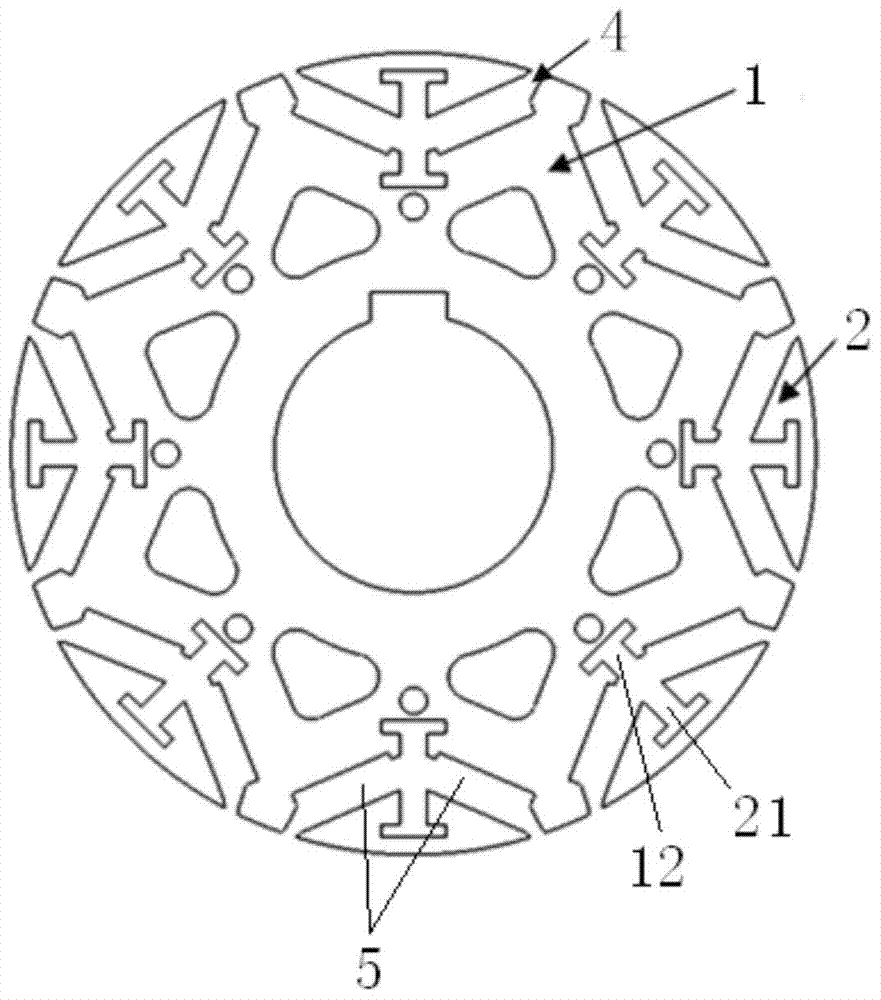
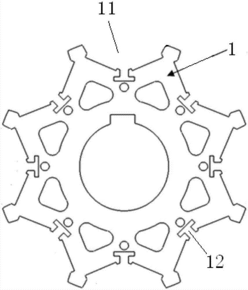
[0027] Such as Figure 2 to Figure 5 As shown, the rotor silicon steel sheet structure of the present invention includes a first silicon steel sheet lamination 1, a second silicon steel sheet lamination 2, and connecting keys 3 arranged in one-to-one correspondence with the second silicon steel sheet lamination 2, and the magnetic permeability of the connecting key 3 Less than the magnetic permeability of the silicon steel sheet, the connecting key 3 is particularly a non-magnetic material. Under this premise, the connecting key 3 can be...


PUM


Abstract

The invention discloses a rotor silicon steel sheet structure which comprises a first silicon steel sheet lamination, a second silicon steel sheet lamination and a connection key, wherein the magnetic permeability of the connection key is lower than that of a silicon steel sheet, the second silicon steel sheet lamination is embedded into a containing groove in the outer peripheral surface of the first silicon steel sheet lamination, the first silicon steel sheet lamination and the second silicon steel sheet lamination are connected through the connection key, two installation grooves used for installing magnetic steel and formed in two sides of the connection key are reserved between the first silicon steel sheet lamination and the second silicon steel sheet lamination, and interstices are formed in the peripheral direction around the central axis of the first silicon steel sheet lamination and between the first silicon steel sheet lamination and the second silicon steel sheet lamination, so that the installation grooves are communicated with the outside through the interstices. The first silicon steel sheet lamination and the second silicon steel sheet lamination are separated in space through the connection key with low magnetic permeability and the interstices, therefore, magnetic lines of force generated by the magnetic steel form a loop in the rotor silicon steel sheet structure difficultly and reach to a stator only through a stator-rotor air gap to be cut by a stator winding to produce torque, and the magnetic energy utilization rate is increased.

Description

technical field [0001] The invention relates to the field of permanent magnet synchronous motors, in particular to the rotor silicon steel sheet structure of the permanent magnet synchronous motors. Background technique [0002] The permanent magnetic field of a permanent magnet synchronous motor is produced by magnets, which are mostly rare earth materials and are expensive. If the magnetic flux leakage coefficient of the magnets can be reduced and the magnetic energy generated by the magnets can be fully utilized, then under the same conditions other conditions can produce Greater torque improves the efficiency of the permanent magnet synchronous motor; conversely, in the case of generating the same torque, a smaller volume of magnetic steel is required, which can reduce the cost of the permanent magnet synchronous motor. [0003] Such as figure 1 As shown, the rotor silicon steel sheet of the existing permanent magnet synchronous motor has an integrated structure. Since ...

Claims


Application Information

Patent Timeline
IPC IPC(8): H02K1/27
Inventor 付林韩千兵郭侃任庆
Owner ANHUI JIANGHUAI AUTOMOBILE GRP CORP LTD
Why Eureka
Try Eureka