
Distributed system monitoring method stepping over data center clusters and system

A distributed system and cross-data center technology, applied in the field of server cluster monitoring, can solve the problems of monitoring system failure, slow response time, monitoring system paralysis, etc., achieve efficient monitoring and management, shorten transmission path, and reduce overhead Effect

Active Publication Date: 2014-03-26
INST OF COMPUTING TECH CHINESE ACAD OF SCI
View PDF5 Cites 21 Cited by
  • Summary
  • Abstract
  • Description
  • Claims
  • Application Information

AI Technical Summary

Problems solved by technology

[0005] (1) A large amount of monitoring data is collected from the lower-level server nodes to the general monitoring node at the same time. At the same time, the general monitoring node also responds to the request for monitoring data from the business side, which undoubtedly greatly increases the input and output pressure of the general monitoring node, and also directly leads to stability. Reduced performance, unable to meet daily business needs well
[0006] (2) The role of nodes in the monitoring system is unique. If there is a problem with the central monitoring node, part of the monitoring system will fail; if the main monitoring server node fails or goes down, the entire monitoring system will be paralyzed
[0007] (3) In the face of business across multiple data centers, it will be difficult for the total monitoring node to span multiple data centers under the bottleneck constraints of the total data volume and architecture, which will greatly slow down the response time and fail to meet real-time requirements
This invention creates a sub-center monitor for each sub-cluster, and pushes the collected internal information of the cluster to the central monitoring server, which still causes the problem of huge network and node I / O of the central monitoring server to be unsolved
It does not meet the personalized monitoring and customization needs of the business, and the dynamic scalability and runtime stability of nodes at each layer are not good

Method used


Image

  • Distributed system monitoring method stepping over data center clusters and system
  • Distributed system monitoring method stepping over data center clusters and system
  • Distributed system monitoring method stepping over data center clusters and system

Examples


Embodiment Construction

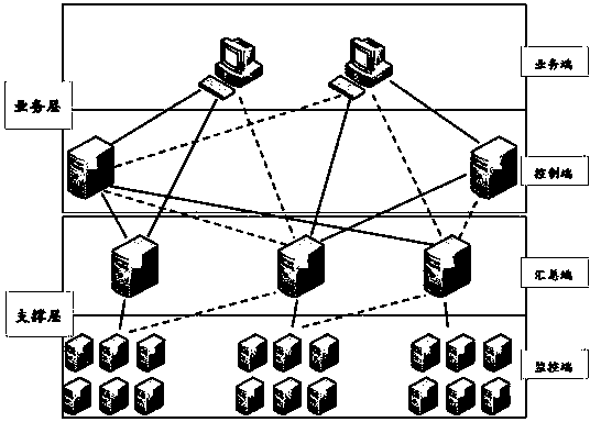
[0082] The monitoring system of the present invention adopts a multi-layer distributed architecture, and the system includes two levels and a monitoring software architecture composed of four module types below. The two layers are the business layer and the support layer (see Appendix figure 1 ), the four software modules are: the business layer includes two types of functional objects: the server running the business monitoring software (referred to as the business end) and the server running the control software server (referred to as the control end); the support layer includes the server running the summary software ( There are two types of functional objects: the summary terminal for short) and the server running the monitoring terminal software (monitoring terminal for short). Each module type includes multiple nodes in the monitoring system.

[0083] Monitoring template (template for short): specifies the information of the data field that the monitoring terminal needs...


PUM


Abstract

The invention relates to a distributed system monitoring method stepping over a data center cluster and a system. The system has a multilayered distributed framework and comprises a business layer, a supporting layer and a monitoring framework; the monitoring framework consists of a business end, a control end, a collecting end and a monitoring end; the business layer comprises two function objects such as the business end and the control end; and the supporting layer comprises two function objects such as the collecting end and the monitoring end. The monitoring framework is managed in a unified manner, is opened stably, is used for cloud computing and steps over a plurality of data centers.

Description

technical field [0001] The present invention relates to the field of server cluster monitoring, and in particular to a monitoring system and method across multiple data centers. Background technique [0002] With the increasing application of cloud computing to various fields of the information industry, the number and scale of data centers on which cloud platforms are based has gradually increased, and businesses running on a single cloud platform span multiple data centers. How to effectively monitor and manage a large number of cluster devices across data centers and regions and ensure the high performance and high availability of the system is a necessary and urgent problem currently facing. [0003] The first monitoring architecture commonly used in the industry is pyramidal. For example, SuperMon, a general-purpose monitoring system software for large-scale Linux clusters developed by the National High Performance Computer Laboratory of a university, is divided into th...

Claims


Application Information

Patent Timeline
Patent Type & Authority Applications(China)
IPC IPC(8): H04L29/08H04L12/26
Inventor 杨庆林孙毓忠
Owner INST OF COMPUTING TECH CHINESE ACAD OF SCI
Learn More