User equipment identifier allocation method, device and system
A technology for user equipment and identification allocation, which is applied in the field of communication and can solve the problems of reducing transmission redundancy, large transmission redundancy, ID conflict, etc.
- Summary
- Abstract
- Description
- Claims
- Application Information
AI Technical Summary
Problems solved by technology
Method used
Image
Examples
Embodiment 1
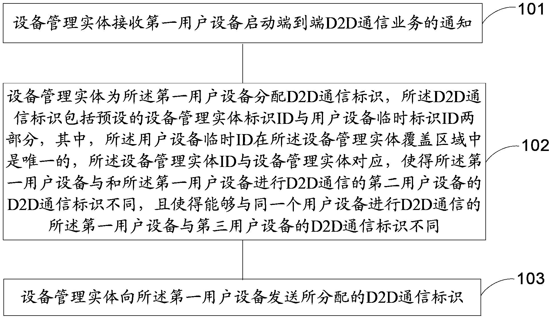
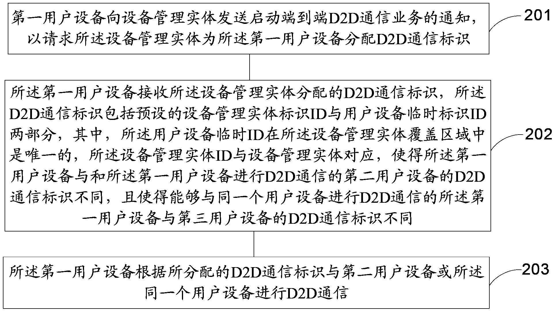
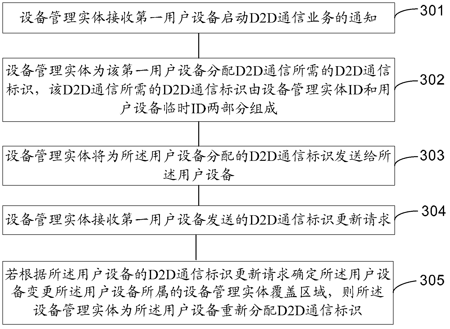
[0111]In this embodiment, a first-level device management entity is set, and the coverage area of the device management entity corresponds to a TA (Tracking Area) area or a plurality of continuous TA areas. If the coverage area of a device management entity corresponds to a TA area , for LTE, the device management entity can be configured on the Mobile Management Entity (MME for short) in the LTE network, that is, the device management entity is a functional unit of the MME, and the coverage area of the device management entity is the same as that of the MME. If a The coverage area of the device management entity corresponds to multiple consecutive TA areas. For LTE, one TA area corresponds to the management area of one MME. Then this device management entity can be configured on one of the MMEs in these continuous TA areas, that is, the device A management entity is a functional unit of one of the MMEs. The device management entity may also be a functional entity in...
Embodiment 2
[0133] This embodiment still takes LTE as an example for illustration, and its principle and implementation method are the same as in Embodiment 1, except that the device management entity is selected to be configured on the base station (or cell), that is, the device management entity is used as a function of the base station (or cell) entities, and the coverage area of each device management entity is the same as that of its corresponding base station (or cell), and the method of presetting the device management entity ID is different. Only the different parts will be described in detail below.
[0134] In the LTE system, when the device management entity is selected to be configured on the base station, the device management entity ID may be determined according to the Physical Cell ID of the base station (or cell) corresponding to the device management entity. Then the D2D communication identifier of the user equipment is: the physical layer identifier of the base station...
Embodiment 3
[0139] In this embodiment, a cellular system is taken as an example for illustration. Its implementation method and principle are the same as in Embodiment 1, except that the equipment management entity is located in a multi-level network, and each level of equipment management entity is located in the coverage area of the upper-level equipment management entity. The device management entity ID includes at least one level, and the device management entity ID of each level is unique in the coverage area of the upper level device management entity. This embodiment only describes the different parts.
[0140] This embodiment is described by taking a two-level device management entity in a cellular system as an example. see Figure 5 , set up a device management entity in area A, area B, area X, etc., and it is a first-level equipment management entity, which can be called equipment management entity A, equipment management entity B, equipment management entity X, and first-l...
PUM
 Abstract
Description
Claims
Application Information
 - R&D
- Intellectual Property
- Life Sciences
- Materials
- Tech Scout
- Unparalleled Data Quality
- Higher Quality Content
- 60% Fewer Hallucinations
Browse by: Latest US Patents, China's latest patents, Technical Efficacy Thesaurus, Application Domain, Technology Topic, Popular Technical Reports.
© 2025 PatSnap. All rights reserved.Legal|Privacy policy|Modern Slavery Act Transparency Statement|Sitemap|About US| Contact US: help@patsnap.com


