Motor stator and permanent magnet rotating electric machine

A motor and stator technology, applied in the field of permanent magnet rotating electrical machines, can solve the problems of high density requirements, reduced insulation distance, reduced insulation distance, etc.

Active Publication Date: 2014-03-26
HITACHI IND EQUIP SYST CO LTD
View PDF10 Cites 10 Cited by
  • Summary
  • Abstract
  • Description
  • Claims
  • Application Information

AI Technical Summary

Problems solved by technology

[0008] Thus, in motors, this creepage surface can cause problems with reduced insulation distances (insulation space distance, creepage distance, etc.)
Especially in the case of miniaturization of the motor, there is a high demand for high density inside the motor, and the insulation distance between the two conductive parts is also reduced. From the perspective of safety and operating performance, the necessary insulation performance Difficult to be guaranteed, this becomes a bigger problem

Method used


Image

  • Motor stator and permanent magnet rotating electric machine
  • Motor stator and permanent magnet rotating electric machine
  • Motor stator and permanent magnet rotating electric machine

Examples


Embodiment

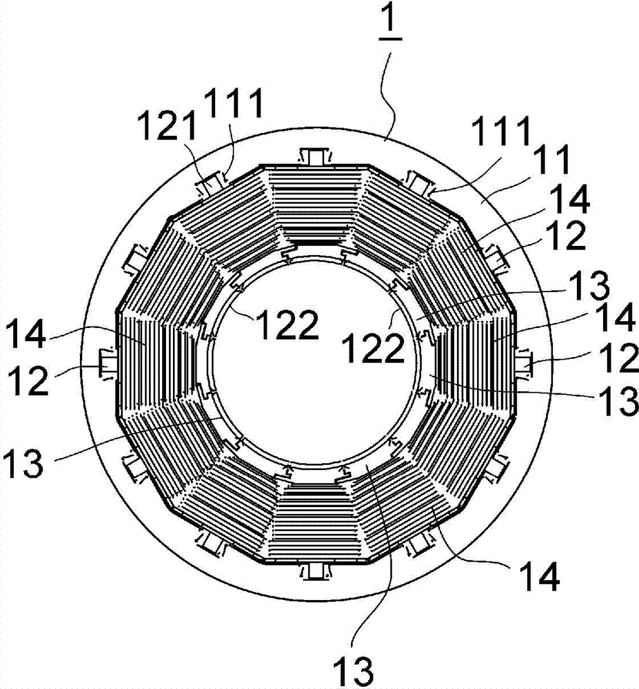
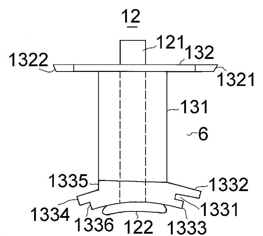
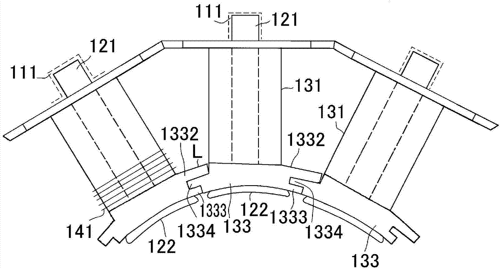
[0057] figure 1 It is a structural diagram showing the stator structure of the main components included in the stator of the motor of the present invention, figure 2 Is to figure 1 A part (single) of the coil bobbin is enlarged to show the structure of the coil bobbin, image 3 It is a configuration diagram that explains the combination of adjacent coil bobbins by combining a plurality of coil bobbins, Figure 4 with Figure 5 It is an exploded perspective view showing the main parts and assembly structure of the yoke core, tooth core, and coil bobbin of the stator of the present invention.

[0058] In these figures, 1 denotes a stator (stator) that interacts with a rotor (not shown) of a motor to generate rotational momentum. The stator includes a cylindrical yoke core (yoke core) 11 and a yoke core disposed thereon. The parts described later inside the cylinder. The stator further includes a plurality of T-shaped tooth cores 12 composed of split cores, a plurality of coil bobbi...


PUM


Abstract

Provided are a stator capable of ensuring the creepage distance and being applicable to a compact motor, and a permanent magnet rotating electric machine. A motor stator (1) is provided with a yoke core (11) and a plurality of tooth cores (12) extending in the radial direction of the core (11). In the motor stator (1), a plurality of bobbins (13) attached to the tooth cores (12) and produced from an insulating material are provided, the bobbin (13) is configured from a body part (131) around which the exciting winding of the stator (1) is wound, and flange parts (132, 133) formed at both ends of the body part (131), and at an end surface in the circumferential direction of the inner diameter-side flange part (132, 133) of the flange parts (132, 133), a fitting section for fitting projecting and recessed sections of the flange parts (132, 133) of adjacent bobbins (13); to each other to thereby connect the plurality of bobbins (13) in the circumferential direction is provided.

Description

Technical field [0001] The present invention relates to a stator of an electric motor and a permanent magnet type rotating electric machine equipped with the stator. Background technique [0002] As a motor, for example, a motor installed in a machine or electronic device like a servo motor, people have never-ending demands on its miniaturization. [0003] As a method of miniaturizing the motor, it is generally effective to increase the number of windings of the coil and increase the density of the coil winding (winding wire). [0004] As one of the means for realizing this method, such a stator structure can be adopted. That is, the stator core constituting the stator (stator) is divided into a plurality of divided cores. Next, a coil (winding) is wound by a predetermined number of times for each divided iron core. Then, according to the required number of slots, the split iron core wound with the coil is assembled into an annular stator. [0005] However, in such a stator structu...

Claims


Application Information

Patent Timeline
Patent Type & Authority Applications(China)
IPC IPC(8): H02K3/46H02K1/18H02K21/16
CPCH02K3/522H02K2203/12H02K1/148
Inventor 酒井俊彦藤岳雅志横山弘树
Owner HITACHI IND EQUIP SYST CO LTD
Why Eureka
Try Eureka