Supercharge Your Innovation With Domain-Expert AI Agents!

Computer optometry unit

A refractometer and computer technology, applied in the field of computer refractometer, can solve problems such as insufficient relaxation and adjustment, large errors, and influence on the accuracy of diopter inspection results

Active Publication Date: 2014-04-02
NINGBO MING SING OPTICAL R & D
View PDF7 Cites 11 Cited by
  • Summary
  • Abstract
  • Description
  • Claims
  • Application Information

AI Technical Summary

Problems solved by technology

[0004] The accuracy of the computer refractometer is affected by many factors, such as poor coordination between the head and eyes of the subject, moving around, and not focusing enough on the target in the refractor, resulting in insufficient relaxation and adjustment, which will inevitably affect the accuracy of the diopter test results Sex, and even the difference in the degree of repeated inspection is large, especially for children, the error of the computer optometry test is large, and the diopter cannot even be checked.

Method used


Image

  • Computer optometry unit
  • Computer optometry unit
  • Computer optometry unit

Examples


Embodiment Construction

[0042] Below in conjunction with specific embodiment, further illustrate the present invention.

[0043] Such as figure 1 The computer optometry shown includes a base assembly 5, a control assembly 2 and a screen assembly 1 are arranged on the platform of the base assembly 5, and a head support assembly 4 is arranged at the front end of the base assembly 5, and the head support assembly 4 is arranged on the platform of the base assembly 5. A three-dimensional translation assembly 6 is arranged between the support assembly 4 and the control assembly 2, and the control assembly 2 completes the automatic or manual detection of both eyes;

[0044] Such as figure 2 and 3 As shown, the three-dimensional translation assembly 6 includes a lifting part, and the front and rear moving parts and the left and right moving parts are arranged on the lifting part, and the monitoring assembly is arranged on the top of the left and right moving parts; the lifting part includes an orientation...


PUM


Abstract

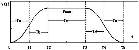
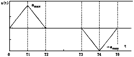
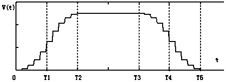
The invention relates to a computer optometry unit which is characterized by comprising a base assembly, a control assembly, a screen assembly, a head support assembly, a three-dimensional translation assembly and a monitoring assembly. The control assembly comprises an electrical control hardware portion and an electrical control algorithm software portion, the electrical control hardware portion drives a stepping motor by subdivision driving of an integrated chip through a high-performance microcontroller and a constant current chopping two-phase stepping motor, the microcontroller inputs pulse and level signals to control the running step number and the direction of the stepping motor, the electrical control software algorithm simulates acceleration and deceleration S-shaped curves by an S-shaped curve acceleration and deceleration control method, simulates a corresponding speed change step curve and calculates the frequency and the execution step number of each discrete point, a PWM (pulse width modulation) functional module inside the microcontroller is configured according to frequency parameters to output square-wave signals under corresponding frequency, the execution step number of the motor is accumulated in the output process, and the stepping motor reaches a specified position after all frequency pulses are outputted.

Description

technical field [0001] The invention relates to an eye measuring device, in particular to a computer optometry instrument. Background technique [0002] The current computer refractor adopts an objective measurement method, which projects an infrared image onto the fundus of the human eye, generates a scattering image on the retina of the human eye, and calculates the diopter of the eye objectively by analyzing the measurement image collected by the CCD. [0003] During the measurement, the operator gently controls the front, back, left, right, up and down movement of the instrument, captures the pupil of the subject's eye, aligns it with the pupil of the eye, presses the measurement button, and the measurement result will be displayed immediately on the screen. [0004] The accuracy of the computer refractometer is affected by many factors, such as poor coordination between the head and eyes of the subject, moving around, and not focusing enough on the target in the refrac...

Claims


Application Information

Patent Timeline
Patent Type & Authority Applications(China)
IPC IPC(8): A61B3/103
Inventor 张光裕林礼平马孟鸿骆晟
Owner NINGBO MING SING OPTICAL R & D
Features
  • R&D
  • Intellectual Property
  • Life Sciences
  • Materials
  • Tech Scout
  • Unparalleled Data Quality
  • Higher Quality Content
  • 60% Fewer Hallucinations
Learn More