
Cubic hydraulic machine

A six-sided top hydraulic, steel plate technology, applied in the application of ultra-high pressure process and other directions, can solve the problems of inability to eliminate the fear of operators and maintenance personnel, disability, etc., to improve reliability and safety, prevent falling off or disintegration effect

Inactive Publication Date: 2014-04-02
GUILIN GUIYE HEAVY IND
View PDF6 Cites 1 Cited by
  • Summary
  • Abstract
  • Description
  • Claims
  • Application Information

AI Technical Summary

Problems solved by technology

[0002] The six-sided top hydraulic press uses the working principle of the six-sided top to push the six hard alloy anvils synchronously through hydraulic pressure to extrude the synthetic material to generate high pressure, and to generate high temperature through low-voltage and high-power current heating to make the internal structure of the synthetic material The process of forming a new superhard material through qualitative change. When the six-sided hydraulic press is working, the working oil pressure can reach up to 100MPa, and the process of boosting, maintaining and releasing pressure is performed repeatedly at high frequency. Once the hinge beam is due to internal casting defects Fatigue fractures caused by reasons such as fatigue, resulting in partial or overall loss of balance and collapse, will inevitably bring great threats to the personnel around the equipment, ranging from disability to fatal. This isolation method can never eliminate the fear of operators and maintenance personnel

Method used


Image

  • Cubic hydraulic machine
  • Cubic hydraulic machine
  • Cubic hydraulic machine

Examples


Embodiment Construction

[0014] The principles and features of the present invention are described below in conjunction with the accompanying drawings, and the examples given are only used to explain the present invention, and are not intended to limit the scope of the present invention.

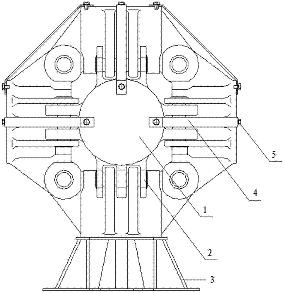
[0015] Such as figure 1 As shown, it includes six hinged beams 1 that are symmetrically distributed in front, rear, left, right, up and down. , gasket 6 and bolt 5, the two ends of the steel plate 4 are tilted, and the tilted position of the steel plate 4 is provided with a long hole 7, and the maximum radial dimension of the long hole 7 is greater than the diameter of the stud on the bolt 5 To the size, the adjacent hinge beam 1 is provided with a screw hole corresponding to the long hole 7 on the steel plate 4, the gasket 6 matches the long hole 7, and the size of the stud on the bolt 5 is the same as the screw hole The dimensions match, the radial dimension of the head of the bolt 5 is greater than the radial di...


PUM


Abstract

The invention relates to a cubic hydraulic machine which comprises six hinge beams symmetrically distributed and hinged in front, rear, left, right, upper and lower spaces. The cubic hydraulic machine is characterized in that protective steel plates are arranged on the bodies of the adjacent hinge beams to connect and fix, wherein each protective steel plate comprises a steel plate, a gasket and a bolt. Both ends of each steel plate upwarp, and long holes are formed in the upwarped parts of the steel plate. Screw holes corresponding to the long holes are formed in the hinge beams. The gaskets are matched with the long holes, the bolts are matched with the screw holes, and both ends of each steel plate are fixed in a way that the bolts penetrate through the gaskets and the long holes in sequence and then are screwed on the screw holes in the adjacent hinge beams. The cubic hydraulic machine provided by the invention has the beneficial effects that the adjacent hinge beams are connected by the protective steel plates, so that a safe tuck net is encircled spatially, and each hinge beam is firmly and effectively tied down to prevent the situation that the hinge beams fall off or break up due to damage, thereby improving the reliability and safety.

Description

technical field [0001] The invention relates to a six-sided roof hydraulic press device, in particular to a six-sided roof hydraulic press. Background technique [0002] The six-sided top hydraulic press uses the working principle of the six-sided top to push the six hard alloy anvils synchronously through hydraulic pressure to extrude the synthetic material to generate high pressure, and to generate high temperature through low-voltage and high-power current heating to make the internal structure of the synthetic material The process of forming a new superhard material through qualitative change. When the six-sided hydraulic press is working, the working oil pressure can reach up to 100MPa, and the process of boosting, maintaining and releasing pressure is performed repeatedly at high frequency. Once the hinge beam is due to internal casting defects Fatigue fractures caused by reasons such as fatigue, resulting in partial or overall loss of balance and collapse, will inevit...

Claims


Application Information

Patent Timeline
Patent Type & Authority Applications(China)
IPC IPC(8): B01J3/06
Inventor 龚世勇廖柳燕胡毅胜
Owner GUILIN GUIYE HEAVY IND
Learn More