Tread brake device

A technology of tread braking and rotational connection, applied in railway braking systems, brakes with brakes, transportation and packaging, etc., can solve the problem of accelerating the wear of the piston sealing ring 35', affecting the stability of device operation, and reducing mechanical transmission Efficiency and other issues, to achieve the effect of improving mechanical transmission efficiency, avoiding rigid impact wear, and stable rotation

Active Publication Date: 2014-04-02
CRRC CHANGZHOU TECH MARK IND CO LTD +1
View PDF7 Cites 9 Cited by
  • Summary
  • Abstract
  • Description
  • Claims
  • Application Information

AI Technical Summary

Problems solved by technology

The tread brake device with this structure has been widely used in rail transit vehicles for more than 20 years. It operates stably and has high reliability, but there are still some parts that are unevenly stressed and easy to wear when there are displacements between some parts. Disadvantages of high maintenance costs
like Figure 9 and Figure 10 As shown, the slider 42' in the tread braking device based on the technical solution of the German patent document DE4117632A1 slides directly on the cylinder 1', and the cylinder 41-1' on the thrust ring 41' is clamped on the slider 42 'In the circular groove 42-1', so the slider is easy to wear, which will affect the stability of the device operation
In addition, the supporting foot 31-2' of the piston is directly hinged with the cam 33', and the cam 33' rotates. When the roller 41-2' is pushed forward, the piston 31' will deflect at this time, and the deflection of the piston 31' will squeeze the piston seal. Ring 35', accelerate the wear of piston sealing ring 35'; at the same time, it will reduce the efficiency of mechanical transmission

Method used


Image

  • Tread brake device
  • Tread brake device
  • Tread brake device

Examples


Embodiment 1)

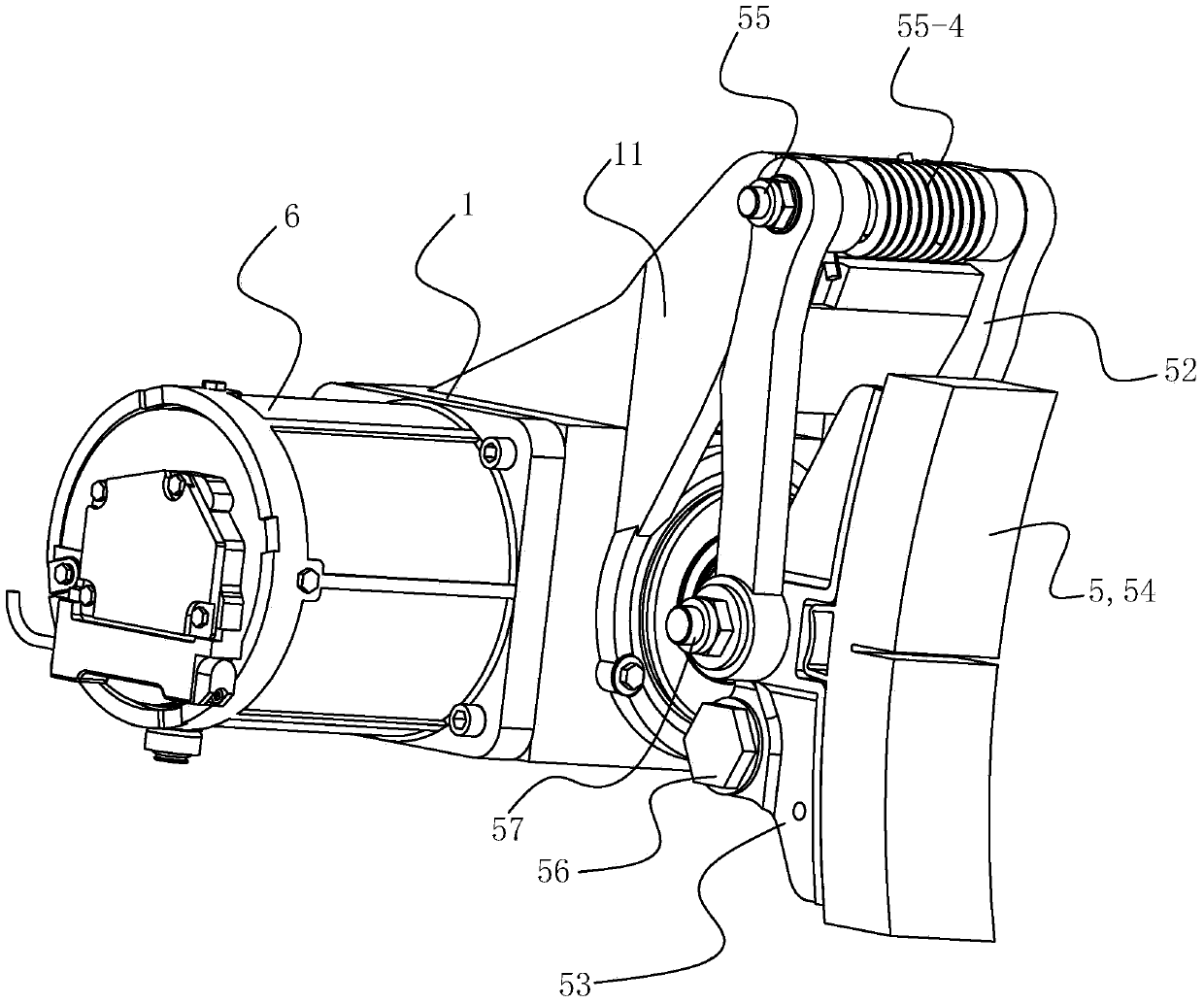
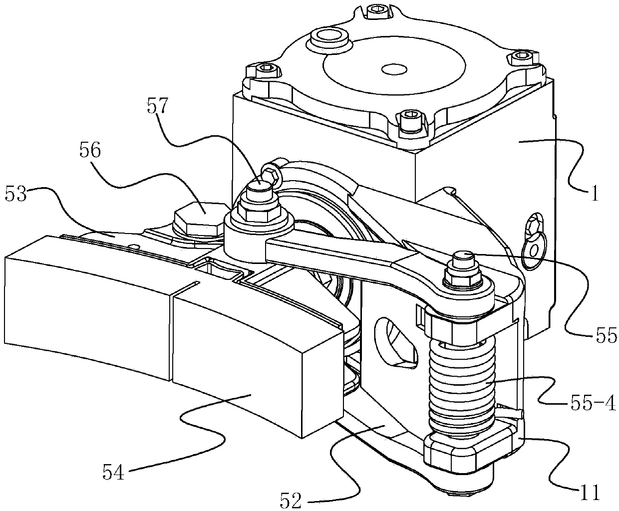
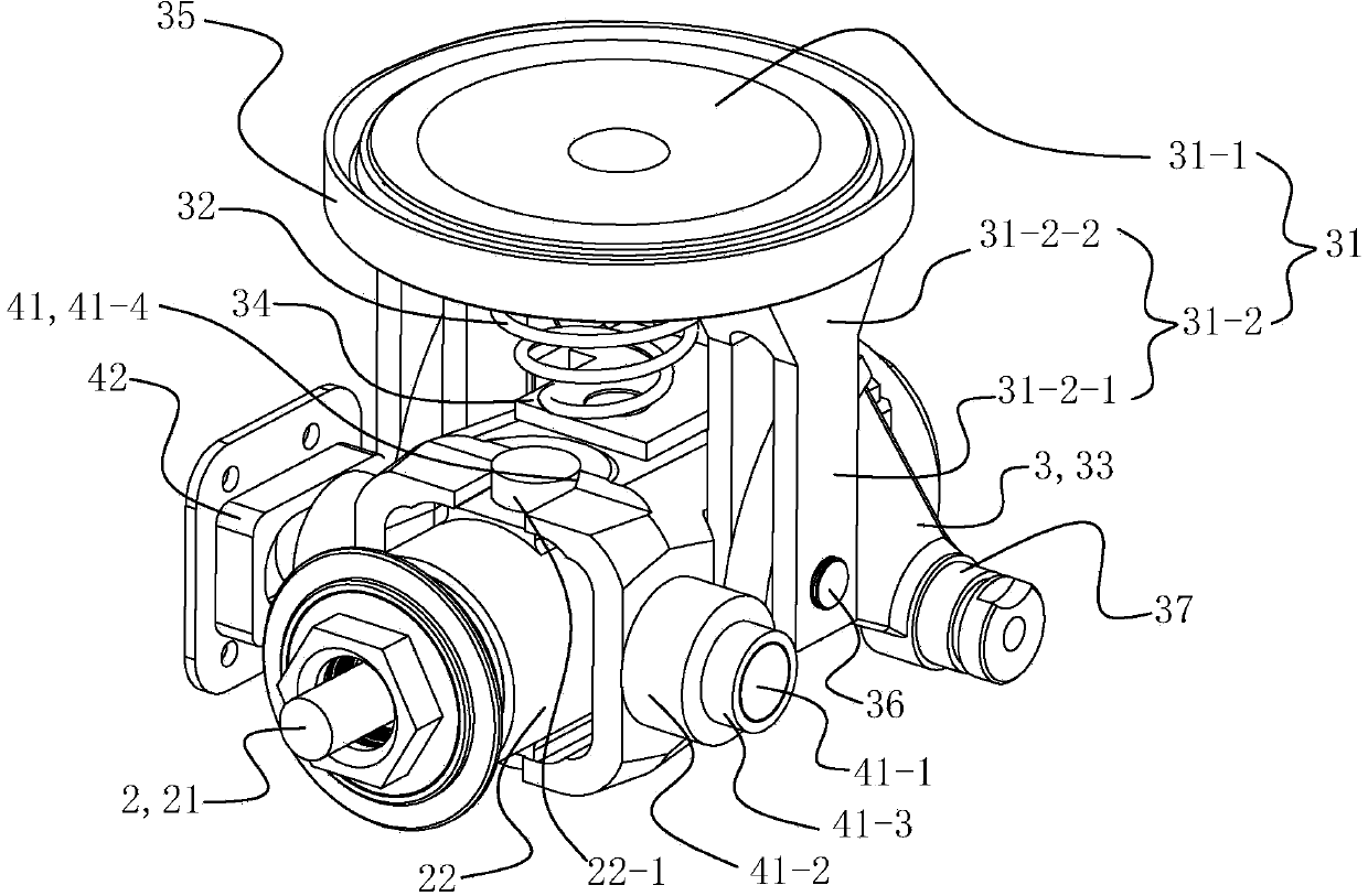
[0041] See figure 2 and image 3 , The tread braking device of this embodiment includes a cylinder body 1, a spindle assembly 2, a force amplification mechanism 3, a thrust ring 41 and a brake shoe swing mechanism 5. The main shaft assembly 2 , the force amplification mechanism 3 and the thrust ring 41 are arranged in the cylinder body 1 . The spindle assembly 2 includes a lead screw 21 and a gap adjustment mechanism 22 . The gap adjustment mechanism 22 is sleeved on the lead screw 21 . The thrust ring 41 is sleeved on the gap adjustment mechanism 22 .

[0042] See Figure 3 to Figure 8 , The force amplification mechanism 3 is a cam mechanism, including a piston 31 and two cams 33 . The piston 31 is elastically disposed in the piston cavity, and the piston 31 includes a piston body 31-1 and two legs 31-2 extending from one side of the piston body 31-1. The rotation center of the cam 33 is rotatably connected to the cylinder body 1, and the edge of the cam 33 is provided...


PUM


Abstract

The invention relates to a tread brake device. The tread brake device comprises a cylinder body, a spindle subassembly, a force amplifying mechanism, a thrust ring and a brake shoe swinging mechanism, wherein the brake shoe swinging mechanism comprises an adjusting head, a suspender, a brake shoe support, a brake shoe and a damping subassembly; the suspender is rotatably connected to the cylinder body; the adjusting head and the brake shoe support are rotatably connected to the suspender; the brake shoe and the damping subassembly are arranged on the brake shoe support; the brake shoe support comprises a left side plate and a right side plate; the adjusting head is sleeved on a lead screw and is connected with a clearance adjusting mechanism; a baffle is arranged on the adjusting head and is positioned between the left side plate and the right side plate; threaded holes are formed in positions, which correspond to the baffle, of the left side plate and the right side plate; the damping subassembly comprises screw covers, compression disc springs and friction blocks; the screw covers are screwed in the threaded holes; the compression disc springs are arranged in inner cavities of the screw covers; and each friction block is clamped between the corresponding compression disc spring and the baffle. The brake shoe of the tread brake device can well cling to a tread of a wheel, and abnormal abrasion of parts due to vibration impact can be avoided.

Description

technical field [0001] The invention relates to a foundation braking device, in particular to a tread braking device of a rail transit vehicle. Background technique [0002] Common forms of foundation braking devices for rail transit vehicles include: a tread braking device that presses a brake shoe against the tread to obtain a braking force, and a disc braking device that clamps a brake disc through a brake pad to obtain a braking force. Tread brake application and release of the brakes is usually accomplished using compressed air: the brakes are applied when the compressed air is charged, and the brakes are released when the compressed air is exhausted. The tread brake device is generally composed of a cylinder block, a spindle assembly, a force amplification mechanism, a gap adjustment mechanism, a thrust ring, and a brake shoe swing mechanism. The piston in the cylinder is driven by the compressed gas to drive the main shaft through the cam to push the brake shoe holde...

Claims


Application Information

Patent Timeline
Patent Type & Authority Applications(China)
IPC IPC(8): B61H1/00
Inventor 伍安旭苟青炳江浪廉超杜利清尹仁华
Owner CRRC CHANGZHOU TECH MARK IND CO LTD
Why Eureka
Try Eureka