Vibration generating set and road speed bump with same

A technology of vibration power generation and speed bumps, which is applied in the direction of mechanical power generating mechanisms, roads, roads, etc., can solve the problems of large power supply line laying engineering, high construction and use costs, and non-concentrated load distribution, etc., to achieve electromechanical energy conversion High efficiency, reduced energy waste and use costs, and large output power

Inactive Publication Date: 2014-04-02
HEBEI UNIV OF TECH
View PDF5 Cites 32 Cited by
  • Summary
  • Abstract
  • Description
  • Claims
  • Application Information

AI Technical Summary

Problems solved by technology

[0004] 1. The electrical equipment is scattered, the power supply line is too long, and the load distribution is not concentrated, resulting in large line loss and low power su

Method used


Image

  • Vibration generating set and road speed bump with same
  • Vibration generating set and road speed bump with same
  • Vibration generating set and road speed bump with same

Examples


Embodiment 1

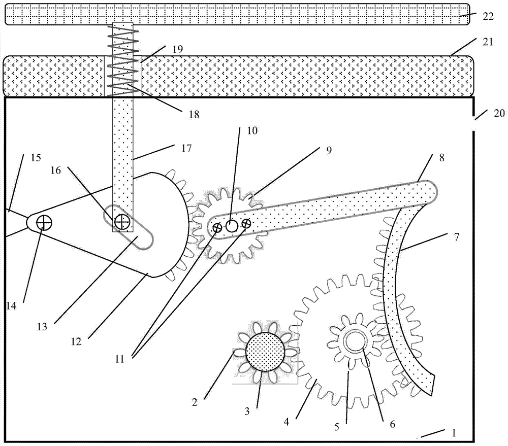
[0029] The structural diagram of the vibration power generation device according to the present invention is as follows: figure 1 As shown, the device is a box structure with a cuboid shape; inside the box, shaft two 10, shaft three 6 and permanent magnet synchronous generator 3 are all fixed on the main inner wall of the box by screws, and the bearing seat 15 is fixed on the box On the inner wall on the left side of the main inner wall, the shaft one 14 is fixed on the bearing seat 15; the one-way bearing is fixed on the shaft of the permanent magnet synchronous generator 3 through key fit, and the gear three 2 is fixed on the one-way bearing through key fit; Gear 2 4 and gear 1 5 are both fitted on shaft 3 6 through keys, gear 1 5 drives gear 2 4 to rotate synchronously, gear 2 4 is close to the inner wall; gear 3 2 meshes with gear 2 4; rack 7 is along the vertical direction Placement, the upper end of the rack 7 and the right end of the swing rod 8 are fixed together by bo...


PUM


Abstract

The invention belongs to a vibration generating set. According to the device, a large sector gear, a small gear and an amplification swing mechanism of a swing rod are used for amplifying the linear displacement of a top rod, then the amplified linear movement is converted into unidirectional rotation motion by a rack and a gear bank, the torque applied to a rotor of a permanent magnetic synchronous power generator is high in frequency, the output electric power is large, and the permanent magnetic synchronous power generator has higher electro-mechanical conversion efficiency, adopts a flat power generator structure, is favorable for mounting, so the size of the generating set is reduced. The pressure mechanical energy generated when a vehicle passes by the speed bump is used for power generation, the vibration generating set has higher power density, is environment-friendly and solves the power supplying problem of road affiliated power utilization facilities, and energy waste caused by centralized power supplying and use cost are reduced.

Description

technical field [0001] The invention relates to a technology for converting pressure mechanical energy into electrical energy when a vehicle passes through a road deceleration belt, in particular to a vibration power generation device and a road deceleration belt with the device. Background technique [0002] There are relatively dense deceleration strips near important road facilities such as road toll stations, and the traffic flow is large. These road facilities are scattered and have a large number of auxiliary electronic and electrical equipment. Therefore, it has important application value to make full use of the pressure when the vehicle passes through the speed bump of the road to drive the generator to supply power for the auxiliary electronic equipment and electrical equipment of the road facilities. [0003] There are many shortcomings in the existing centralized power supply technology for road facilities: [0004] 1. The electrical equipment is scattered, the ...

Claims


Application Information

Patent Timeline
IPC IPC(8): F03G7/08E01F9/047E01F9/529
CPCF03G7/08
Inventor 王志华王莉王博文
Owner HEBEI UNIV OF TECH
Why Eureka
Try Eureka