
Inter-tube-bundle high-temperature high-pressure vapor-liquid two-phase flow pattern experimental device and flow pattern identification method

A high-temperature, high-pressure, experimental device technology, applied to measuring devices, fluid dynamics tests, instruments, etc., can solve problems that do not involve boiling, heat transfer, vapor-liquid two-phase flow between high-pressure tube bundles

Active Publication Date: 2014-04-02
HARBIN ENG UNIV
View PDF7 Cites 34 Cited by
  • Summary
  • Abstract
  • Description
  • Claims
  • Application Information

AI Technical Summary

Problems solved by technology

The existing flow pattern classification methods are all limited by experimental conditions, operator experience and flow pattern identification technology, so they can only conduct qualitative analysis on the two-phase flow pattern under specific conditions, and most of the existing research is limited to low pressure. The flow in the tube under the adiabatic condition does not involve the boiling heat transfer vapor-liquid two-phase flow between the high-pressure tube bundles, and the boiling heat transfer vapor-liquid two-phase flow pattern discrimination between the tube bundles is very important for large industrial steam generators, boiling tubes, boilers, nuclear reactors, etc. The safe and economical operation of heat exchange equipment is of great significance

Method used


Image

  • Inter-tube-bundle high-temperature high-pressure vapor-liquid two-phase flow pattern experimental device and flow pattern identification method
  • Inter-tube-bundle high-temperature high-pressure vapor-liquid two-phase flow pattern experimental device and flow pattern identification method
  • Inter-tube-bundle high-temperature high-pressure vapor-liquid two-phase flow pattern experimental device and flow pattern identification method

Examples


Embodiment Construction

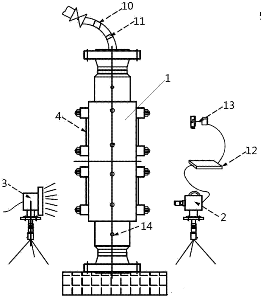
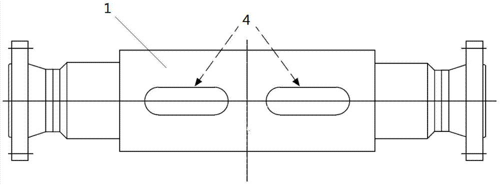
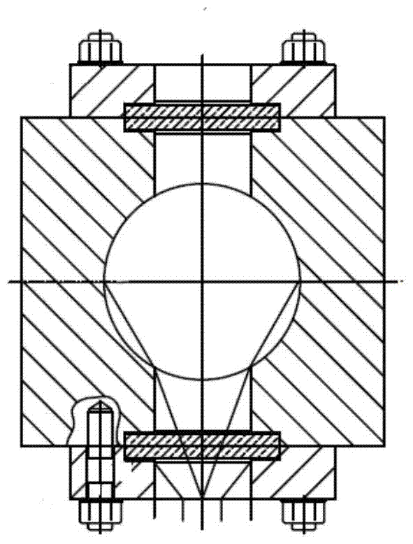
[0029] Such as figure 1 , figure 2 As shown, there are upper and lower two visualization windows 4 symmetrically opened on the front and rear sides of the pressure vessel 1, as shown in image 3 As shown, the cross section of the window is square on the outside and circular on the inside, and the window is provided with window glass. When implemented, the window is 398mm high, 100mm wide, and the upper and lower window spacing is 368mm. Such as figure 1 As shown, the laser generator 3 is located on the rear side of the pressure vessel 1, corresponding to the position of the visualization window on the rear side of the pressure vessel, and the high-speed camera 2 is located on the front side of the pressure vessel 1, corresponding to the position of the visualization window on the front side of the pressure vessel. The laser generator and high-speed camera are installed on the bracket, and the laser generator and high-speed camera can move up and down. Such as Figure 4 As...


PUM


Abstract

The invention relates to an inter-tube-bundle high-temperature high-pressure vapor-liquid two-phase flow pattern experimental device and a flow pattern identification method. An upper visualization window and a lower visualization window are symmetrically formed in the front side and the rear side of a pressure container of the experimental device; a laser generator and a high-speed video camera are arranged corresponding to the visualization windows; electric heating tubes are arranged in the pressure container; thermocouple sensors are arranged on the electric heating tubes; pressure sensors, a liquid level sensor and double-headed conductive probes are arranged on the pressure container; a flowmeter and a sheathed thermocouple are arranged at an inlet tube and an outlet tube of the pressure container; a conducting wire of an electric heating control system penetrates through the outer shell of the pressure container and is connected with the electric heating tubes; a conducting wire of a data acquisition system is connected with the measurement sensors and the high-speed video camera. The data acquisition system acquires shot images and sensor signals; a vapor-liquid two-phase flow pattern map is obtained by performing digital processing on the shot images; a quantitative relationship between fluid parameters and vapor-liquid two-phase flow patterns is established.

Description

technical field [0001] The invention relates to a high-temperature and high-pressure vapor-liquid two-phase flow pattern experiment device between tube bundles and a flow pattern discrimination method. Background technique [0002] The phenomenon of multiphase flow exists widely in nature and in modern industrial production processes, and is closely related to human life and production activities. Vapor-liquid two-phase flow phenomenon is common in heat exchange equipment in chemical industry and power engineering, as well as in oil and gas gathering and transportation pipelines. Two-phase flow has different flow forms, namely flow patterns, in different environments. The two-phase flow pattern greatly affects the flow characteristics and heat and mass transfer characteristics of vapor-liquid two-phase flow, and also has a great influence on the accurate measurement of flow parameters and the operating characteristics of the two-phase flow system. In the early stage of rese...

Claims


Application Information

Patent Timeline
Patent Type & Authority Applications(China)
IPC IPC(8): G01M10/00
Inventor 孙宝芝郑陆松李彦军杨龙滨张国磊李晓明张鹏宋福元杨柳韩文静张宇史建新
Owner HARBIN ENG UNIV
Features
  • Generate Ideas
  • Intellectual Property
  • Life Sciences
  • Materials
  • Tech Scout
  • Unparalleled Data Quality
  • Higher Quality Content
  • 60% Fewer Hallucinations
Learn More