
Light guide plate and preparation method thereof, backlight module and display device

A light guide plate and backlight technology, which is applied in the fields of light guide plate and its preparation, backlight module, and display device, and can solve problems such as easy bending, cumbersome assembly process, and performance impact

Inactive Publication Date: 2014-04-02
BEIJING BOE OPTOELECTRONCIS TECH CO LTD
View PDF5 Cites 3 Cited by
  • Summary
  • Abstract
  • Description
  • Claims
  • Application Information

AI Technical Summary

Problems solved by technology

[0005] Side-lit backlight modules generally include light sources, light guide plates, reflectors, diffusers, and prisms; when assembling the backlight module, the reflector needs to be placed under the light guide, and the diffuser And the prism sheet is set above the light guide plate, and the light source is set on the side of the light guide plate, the assembly process is relatively cumbersome
In addition, because the light guide plate is relatively light and thin, it is easy to bend, which will have a certain impact on its performance in the reliability test

Method used


Image

  • Light guide plate and preparation method thereof, backlight module and display device
  • Light guide plate and preparation method thereof, backlight module and display device
  • Light guide plate and preparation method thereof, backlight module and display device

Examples


Embodiment Construction

[0035] The following will clearly and completely describe the technical solutions in the embodiments of the present invention with reference to the accompanying drawings in the embodiments of the present invention. Obviously, the described embodiments are only some, not all, embodiments of the present invention. Based on the embodiments of the present invention, all other embodiments obtained by persons of ordinary skill in the art without making creative efforts belong to the protection scope of the present invention.

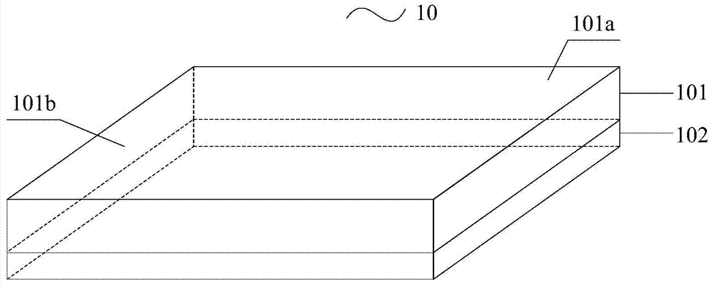
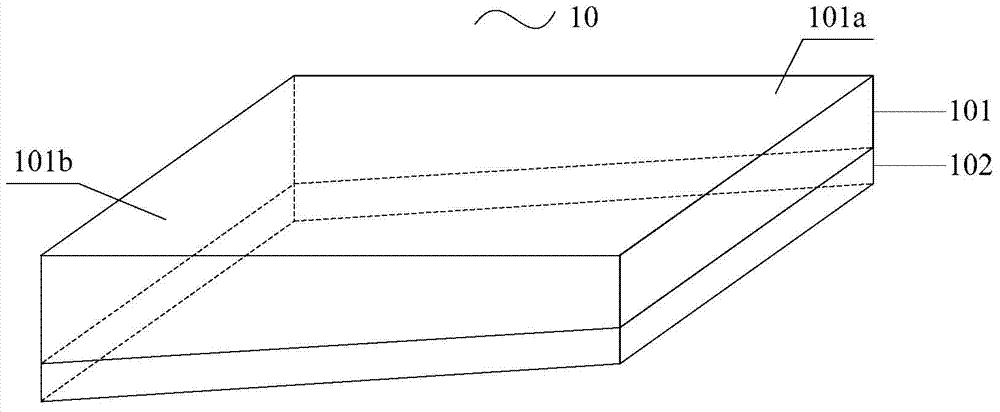
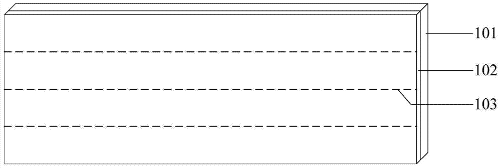
[0036] An embodiment of the present invention provides a light guide plate 10, such as Figure 1(a) and 1(b) As shown, the light guide plate body 101 and the reflective layer 102 are included, and the light guide plate body 101 and the light reflective layer 102 are integrally formed. The light guide plate body 101 includes a light exit surface 101a, a bottom surface opposite to the light exit surface 101a, and a plurality of side surfaces adjacent to the lig...


PUM


Abstract

The embodiment of the invention provides a light guide plate and a preparation method thereof, a backlight module and a display device, and relates to the technical field of display. The component number of the backlight module can be reduced, and the poor deformation of the light guide plate is improved. The light guide plate comprises a light guide plate body and a reflecting layer, and the light guide plate body and the reflecting layer are integrally formed. The light guide plate body comprises a light emergent face, a bottom face and a plurality of side faces, wherein the bottom face is opposite to the light emergent face; the side faces are adjoined between the light emergent face and the bottom face; at least one of the side faces of the light guide plate body is a light incident face; the reflecting layer is arranged by clinging to the bottom face of the light guide plate body; the reflecting layer is made of a material with light reflection characteristics. The light guide plate is used for manufacturing the display device.

Description

technical field [0001] The invention relates to the field of display technology, in particular to a light guide plate and a preparation method thereof, a backlight source module and a display device. Background technique [0002] A Liquid Crystal Display (LCD for short) has become a mainstream product in flat panel displays due to its advantages of thinness, low cost, and electric drive. Since the liquid crystal itself does not emit light, it is necessary to install a backlight module in the LCD, and the thickness of the backlight module directly determines the thickness of the LCD. [0003] According to the position of the light source, the backlight module can be divided into direct type and edge type. [0004] Among them, the edge-lit backlight module can diffuse light to the entire display panel by setting a light source at the edge of the liquid crystal display panel and converting it into a surface light source by using a light guide plate. Compared with the direct-l...

Claims


Application Information

Patent Timeline
IPC IPC(8): G02B6/00F21S8/00F21V8/00G02F1/13357F21Y101/02F21Y115/10
Inventor 姜太声权宁万
Owner BEIJING BOE OPTOELECTRONCIS TECH CO LTD
Learn More