Water flow inductive switch

A technology of water flow induction and switching, which is applied in the field of induction switching, can solve the problems of insensitivity of magnetic induction circuit boards, short service life, and rusting of iron filings, and achieve sensitive and stable induction pressure signals, sensitive induction pressure signals, and easy to use good effect

Active Publication Date: 2014-04-02
佟勇华
View PDF5 Cites 5 Cited by
  • Summary
  • Abstract
  • Description
  • Claims
  • Application Information

AI Technical Summary

Problems solved by technology

However, the existing water flow sensor switch has been circulated in the market for a period of time and has the following defects: 1. The above-mentioned magnet is placed in the water flow chamber, and after a period of use, iron filings in the water are easily absorbed around the magnet. Moreover, the iron filings absorbed will also rust, which will increase the weight of the magnet and weaken the magnetism, resulting in insensitive induction of the magnetic induction circuit board and short service life.
2. The spring material is often made of metal with iron, which is not only easy to magnetize, but also has the phenomenon of absorbing iron filings and accumulating rust like the above-mentioned magnets, and it is also easy to be corroded and rusted after a period of use, and elastic stagnation occurs. It also makes the magnetic induction circuit board insensitive and has a short service life
3. Due to the small size of the springs, these springs made by the current technology will experience rebound fatigue after a period of use, and the rebound force and length will change, resulting in a shift in the sensed pressure threshold, large use errors, and poor results.
4. Based on the linear relationship between the above-mentioned spring pressure and the amount of expansion and contraction, when the water pressure is close to the pressure threshold of the induction, that is, the spring compression makes the distance between the magnetic induction circuit board and the magnet at the induction zero threshold, it is easy to cause the magnetic induction circuit board to switch. Signal jumps frequently

Method used


Image

  • Water flow inductive switch
  • Water flow inductive switch
  • Water flow inductive switch

Examples


Embodiment 1

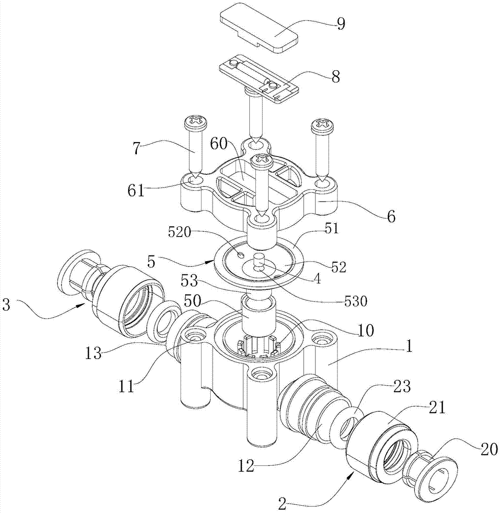
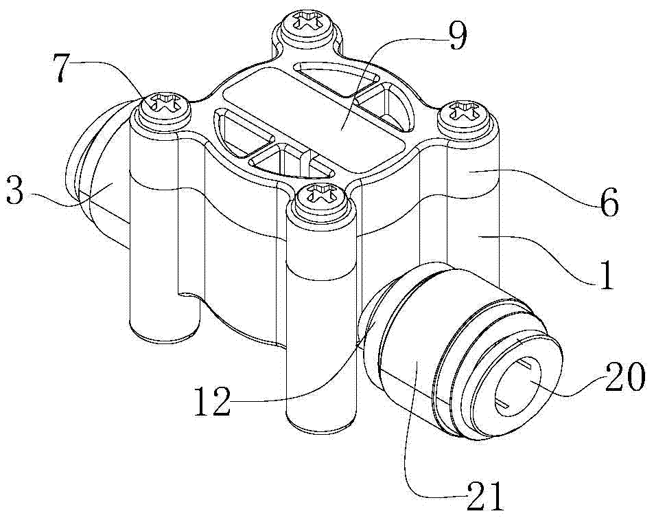
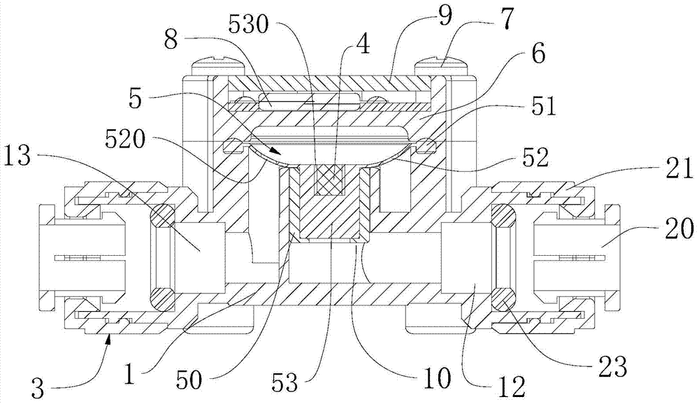
[0025] Such as figure 1 , figure 2 , image 3 , Figure 4 and Figure 5 A water flow sensor switch is shown, which includes a housing, an elastic reset film 5 , a magnetic block 4 and a magnetic induction circuit board 8 . The housing is square as a whole and consists of a main housing 1 with an open top and an upper cover 6 sealingly covering the opening at the top of the main housing 1. Four screw holes 11 are arranged longitudinally along the four corners of the square main housing 1. Correspondingly, four through holes 61 are provided along the four corners of the square top cover 6 for the screws 7 to pass through, and the top cover 6 is fastened above the main casing 1 by four screws 7 to secure the main casing The opening at the top of the body 1 is sealed, and the way of sealing and covering is convenient for disassembly. Of course, for the housing, other known sealing and covering methods can also be used, and even the upper cover 6 and the main housing 1 can be...

Embodiment 2

[0032] Such as Figure 6 As shown, on the basis of Embodiment 1, the shape of the annular deformable membrane 52 of this embodiment is surrounded by an arc-shaped concave surface with an inner notch pointing obliquely upward, and the annular deformable membrane 52 in this embodiment is provided with two Pressure balance hole 520 .

[0033] The material of the annular deformable membrane 52 of the present embodiment is the following silica gel of raw material composition: 95 parts of vinyl silicone rubbers, 20 parts of fumed silica, 2 parts of diphenylsilanediol, 152 parts of titanium dioxide and benzoyl peroxide 2 servings. The above are all calculated in parts by weight and made through the existing silica gel manufacturing method.

Embodiment 3

[0035] Such as Figure 6 As shown, on the basis of Embodiment 2, the difference between this embodiment and Embodiment 2 is that the material of the annular deformable membrane 52 is silica gel with the following raw material components: 100 parts of vinyl silicone rubber, 22 parts of fumed silica, 3 parts of diphenylsilanediol, 148 parts of titanium dioxide and 1 part of benzoyl peroxide. The above are all calculated in parts by weight and made through the existing silica gel manufacturing method.


PUM


Abstract

The invention relates to an inductive switch for inducing a water flow pressure signal in a flowing water pipeline. The water flow inductive switch comprises a casing with a water inlet and a water outlet, an elastic resetting membrane element, a magnetic block and a magnetic induction circuit board, wherein a mounting cavity is formed in the inner side of the casing; the water inlet of the casing is communicated with the water outlet through the mounting cavity; the elastic resetting membrane element and the magnetic block are positioned on the inner side of the casing; a pushing and pressing column part which is elastically plugged in the mounting cavity is arranged at the lower part of the elastic resetting membrane element, and an annular deformation membrane is arranged at the upper part of the elastic resetting membrane element, and surrounds and is fixedly connected to the outer peripheral wall of the top of the pushing and pressing column part; the top of the annular deformation membrane is propped against the inner wall of one side of the casing; the magnetic induction circuit board is positioned on the outer side of the casing, and corresponds to the annular deformation membrane; the magnetic block is embedded into the top end part of the pushing and pressing column part; an induction gap changing along with the deformation state of the annular deformation membrane is reserved between the magnetic block and the magnetic induction circuit board. The water flow inductive switch is novel in structure, and has the advantages of high pressure signal induction sensitivity and stability, good using effects, long service life and the like.

Description

technical field [0001] The invention relates to a pressure inductive switch, in particular to an inductive switch used in a water flow pipeline to sense water flow pressure signals. Background technique [0002] The water flow sensor switch is a sensor switch that senses the pressure signal of the water flow. When the pressure is bounded by a certain threshold, exceeds a certain threshold or is less than a certain threshold, the sensor circuit board will obtain the corresponding sensor signal, convert and output the electrical signal. [0003] An existing water flow induction switch is made by the principle of magnetic induction, and receives a water pressure signal through a magnet and a spring structure installed in the water flow cavity, and the magnet and the spring are all soaked in water. When the water flow pressure is high, the spring will be automatically compressed to make the magnet close to the magnetic induction circuit board, so that the magnetic induction circ...

Claims


Application Information

Patent Timeline
Patent Type & Authority Applications(China)
IPC IPC(8): H01H35/34H01H36/00
Inventor 佟勇华王星照
Owner 佟勇华
Why Eureka
Try Eureka